2-16
u
Installation
R
ACK
M
OUNT
I
NSTALLATION
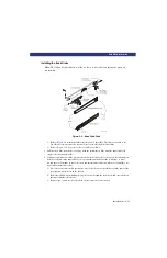
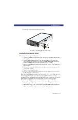
9) If binding occurs, loosen the four screws that secure the slides to the front rails and the four
screws that secure the slides to the rear rails.
10) If necessary, repeat steps 11 and 12 until the PowerLoader chassis does not bind against the
slides.
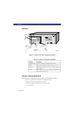
11) Slide the PowerLoader into the rack, and locate the proper position for one clip nut behind the
upper hole in each panel extension. Pull the PowerLoader outward, and install 10-32 clip nuts.
12) Slide the PowerLoader into the rack, and install and tighten one 10-32 thumb screw through
each panel extension into the clip nuts.
This completes the mechanical installation. Refer to the User/Installation manual for
information about electrical and SCSI connections.
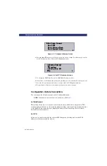
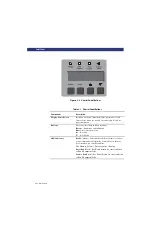
Note:
The options described in this table represent the version of the firmware in use
when this manual was written. If the options displayed on your Control Panel differ from
those described here, contact your Technical Support Representative.
Summary of Contents for LXLS10
Page 1: ......
Page 4: ...xii u Preface PREFACE...
Page 8: ...iv TABLE OF CONTENTS CONT D...
Page 10: ...x LIST OF TABLES CONT D...
Page 18: ...1 6 u Introduction TAPE CARTRIDGE MAGAZINE...
Page 86: ...A 4 u Specifications SPECIFICATIONS Declaration of Conformity...
Page 90: ...Index 2 INDEX...

