Operation
t
3-7
F
RONT
P
ANEL
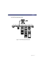
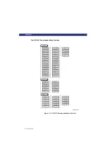
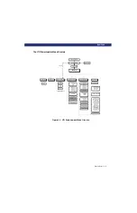
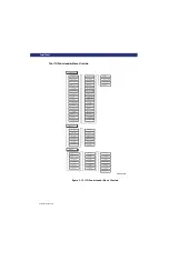
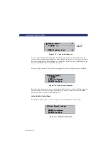
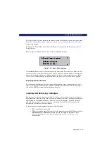
The DLT/SDLT PowerLoader Menu Structure
Figure 3-7. DLT/SDLT PowerLoader Menu Structure
Power Up Displays
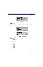
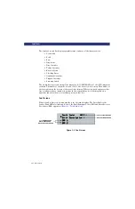
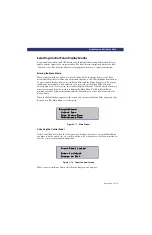
Default Display
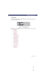
Fault Display
Panel Lock
Main Menu
Load/Unload
Show Status Menu
Maintenance Menu
Configuration Menu
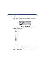
Show History Menu
Unlock Door
From/To
Library
SDLT1
SDLT2
Map Info
Statistics
Error History
Initial Config.
Config. History
Set Unlock Code
Set Default
Set Reserved Slots
Security Menu
Clean Drive
- Cleaning
- Using
Diagnostics
- Cartridge Cycle
- Friction Test
- Tach Feedback
- Scanner Feedback
Demo Menu
Flash Update
Novram Update
Clock Update
Flash SDLT
Set Data Format
Set SCSI
- Library Parity
- Library Bus ID
- SDLT1 Bus ID
- SDLT2 Bus ID
Set Element Base
- Transport
- Storage
- Transfer
Set Identification
- Vendor ID
- Product ID
Reboot Module
Set Baud Rate
Set Serial Number
Set Unload Mode
Set Date
Set Time
Set Auto Clean Mode
Set Special Config.
- TUR Reporting
- Init Element Status
- Unit Attn. Report
- Element Base
- Label Size
- Label Alignment
- Abort Move Status
- SCSI - Mode
- Post Errors
- Tape Alert Mode
- Clean Threshold
- Auto Home
Set Negotiation
- Negotiation Mode
- Transfer Rate
- Bus Width
Set Library Mode
Summary of Contents for LXLS10
Page 1: ......
Page 4: ...xii u Preface PREFACE...
Page 8: ...iv TABLE OF CONTENTS CONT D...
Page 10: ...x LIST OF TABLES CONT D...
Page 18: ...1 6 u Introduction TAPE CARTRIDGE MAGAZINE...
Page 86: ...A 4 u Specifications SPECIFICATIONS Declaration of Conformity...
Page 90: ...Index 2 INDEX...


