Operation
t
3-1
Chapter 3
Introduction
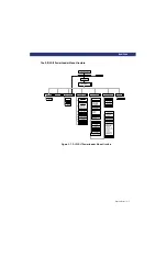
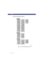
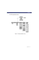
This chapter describes operating the PowerLoader, including using the Control Panel
buttons and indicators, and navigating through the menu structure.
Front Panel
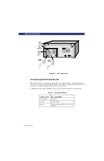
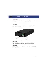
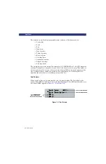
The front panel includes the power switch, the magazine door, and the Control Panel,
which has buttons, a display and indicators.
Figure 3-1. Front Panel
Power Switch
The push-on, push-off power switch controls the supply of AC power to the PowerLoader.
When the power is on, the backplane of the Control Panel display is illuminated.
Control Panel
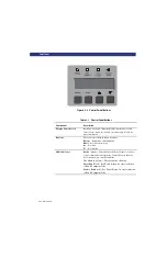
The Control Panel consists of four LED indicators, a 4-line by 20-character backlit LCD
display, and four buttons.
E nter
Esc ape
Ready
Use
Cleane r
Dri ve
F ault
Loa der
Fault
Magazine
Door
Power Switch
Control Panel
Operation
Summary of Contents for LXLS10
Page 1: ......
Page 4: ...xii u Preface PREFACE...
Page 8: ...iv TABLE OF CONTENTS CONT D...
Page 10: ...x LIST OF TABLES CONT D...
Page 18: ...1 6 u Introduction TAPE CARTRIDGE MAGAZINE...
Page 86: ...A 4 u Specifications SPECIFICATIONS Declaration of Conformity...
Page 90: ...Index 2 INDEX...


