background image

E-025-2-E

2

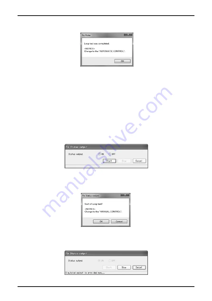
④ Click "Stop" to stop the simulated output. Then a message box (Fig. 93) is displayed. Click "OK" .

Fig.93

⑤ The window for setting the simulated output value is displayed. To exit, click "Cancel".

3.7.2.3 Status Output Loop Test (Fix Status output)

This puts status output into a simulated output state, and conducts a loop test on the output line.
This test creates simulated output regardless of the process state. If the flowmeter's output is used to 
control valves or other such parts, change the control loop to manual control for the sake of safety, 
and so that the control loop cannot be influenced by the flowmeter's output.

① Click "Diag/Service (T)" from the menu, and select "Fix Status output" from the list of "Loop test", 

then the following window (Fig. 94) will be displayed.

Fig.94

② Select the simulated output state. By clicking "Start", a message box (Fig. 95) will be displayed. 

When you click "OK", the analog output is generated.

Fig.95

③  During  simulated  output,  a  message,  "Simulated  output  is  provided  now  ..."  is  displayed  at  the 

bottom of the window as shown in Fig. 96.

Fig.96

Summary of Contents for EL 2310-0BE Series

Page 1: ...MODEL EL 2310 0BE Applicable Flowmeter OVAL Electromagnetic Flowmeters For the installation of application software LinkTop and the interface driver refer to Ins No E 020IMC Smart Communication Unit...

Page 2: ...e protect 17 3 6 Menu Setup Settings 18 3 6 1 Flow Rate Parameter Flow parameter 19 3 6 1 1 Nominal Diameter Nominal diameter 19 3 6 1 2 Measuring Range Flow range 20 3 6 2 Transmitter Variables Field...

Page 3: ...etting Accumulated Total Flow Total flow set 46 3 8 Menu Maintenance Maintenance 47 3 8 1 Maintaining Transmitter Maintenance xmtr 48 3 8 1 1 Error Log Display Error log 48 3 8 1 2 Transmitter Interna...

Page 4: ...text to bring the user s attention to important information CAUTION Caution statements inform the user of hazards or unsafe practices which could result in minor personal injury or product property d...

Page 5: ...the interface driver software refer to Installation Procedure Manual The driver software in the CD ROM is intended for an application of Bell202 Communication Interface for OVAL Smart Communication Un...

Page 6: ...not have a built in RL an external RL needs to be connected in series Tie point Terminal Block Fig 2 2 In Case of Bell202 Communication LINE NEUT 4 to 20mADC OVAL Electromagnetic Flowmeter Receiving I...

Page 7: ...g RS485 communication the RS485 communication interface available on the market shall be used When using Bell202 communication the Bell202 communication interface for OVAL Smart Communication Unit EL2...

Page 8: ...s what the LinkTop window looks like The communication status is indicated at the bottom left of the screen as During communications SEND RECEIVE WAIT Communications interrupted IDLE Fig 4 Menu PC to...

Page 9: ...face port number is unknown open Windows Device Manager and find the port number from the list of Port COM and LPT Click here Then select the corresponding specification baud rate from the Speed list...

Page 10: ...tion If Polling address of the flowmeter is unknown confirm Polling address by the operation of the flowmeter Reference Flowmeter Instruction Manual Communication Function Fig 8 A message box shown as...

Page 11: ...minating the Connection To terminate connection between the flowmeter transmitter and LinkTop follow the procedure given below Click on Disconnect D Shift F3 as shown in Fig 12 Fig 12 At the message b...

Page 12: ...own in Fig 14 Fig 14 3 4 Terminating LinkTop To exit LinkTop click File F from the menu then select Exit E A message box as shown in Fig 15 appears Click OK to confirm and the application software win...

Page 13: ...logging and Write Protect mode Fig 16 3 5 1 Processing Value Measurements View field device variables Click Process Variables V from the menu then select View field device variables The following win...

Page 14: ...select Active then a tool bar as shown in Fig 18 will appear underneath the menu If there is a problem with the flowmeter transmitter then an error message will be displayed in the window under the p...

Page 15: ...t Percent flow rate from the Proccess Variables V menu Fig 21 Click the button of the tool bar or Chart and Recording Chart Percent flow rate from the menu then the window as shown in Fig 20 is displa...

Page 16: ...n as well If you click the button of the tool bar or Chart and Recording Recording Start in the menu the following dialog box Fig 22 is displayed Select the disk and folder to create a file enter a fi...

Page 17: ...and time Percent flow rate Flow rate Flow velocity Fig 25 Write protect shows whether parameter change of the transmitter is available or not Mode Detail SW1 4 Setting Not write protected Enables chan...

Page 18: ...l not be possible to set the various parameters transmitter information and so on Close these windows before making settings For the actual screen refer to Fig 26 Fig 26 Setup Flow parameter Nominal d...

Page 19: ...the changed setting values in the flowmeter s output If the flowmeter s output is used to control valves or other such parts as safety protocol change that control loop to manual control so that the c...

Page 20: ...and to reflect the changed setting values in the flowmeter s output If the flowmeter s output is used to control valves or other such parts as safety protocol change the control loop to manual control...

Page 21: ...cut value with 5 hysteresis ON OFF I F suppress factor Suppress fluctuation of flow output due to impulse like noise Sets the suppression amount of fluctuation with percent value to the measuring ran...

Page 22: ...nge the control loop to manual control so that the control loop cannot be influenced by the flowmeter s output Fig 34 The message box Fig 35 is displayed after changing the setting values Click OK to...

Page 23: ...owing window Fig 39 will be displayed Fig 38 The message box Fig 38 is displayed after changing the setting values Click OK to complete the setting process Enter numeric values for respective items Se...

Page 24: ...and full scale flow Weight Calculate with pulse weight Frequency Weight Freq factor Full scale frequency of pulse output Valid when pulse output mode is Frequency Set value display area is highlighted...

Page 25: ...by the flowmeter s output Select for respective items Setting item Detail Setting range Status output func Status output selection Select from the right column No Function No function Contact output...

Page 26: ...ixed output state Analog Pulse Contact ON OFF Self diag in progress Self diagnosis in process ON OFF NOTE 1 When setting error and alarm as status output click ON 2 Error output is valid only when Sta...

Page 27: ...he right column No Function Normal output Downscale Hold by outputting 2 4mA Zero Hold by outputting 4 0mA Hold Hold current value just before occurrence of error Upscale Hold by outputting 21 6mA No...

Page 28: ...er s output If the flowmeter s output is used to control valves or other such parts as safety protocol change the control loop to manual control so that the control loop cannot be influenced by the fl...

Page 29: ...ow range Flow range Metering range Only for reference Click OK after the setting is completed to display the message box Fig 52 Click OK here to change the settings to the inputted values and to refle...

Page 30: ...ic diagnosis of coil and exciting frequency ON OFF Measurement signal Sets periodic diagnosis of measurement signal ON OFF Empty pipe Sets periodic diagnosis of detecting empty measurement pipe ON OFF...

Page 31: ...Select from the right column JIS 10K JIS 20K JIS 30K ANSI ASME150 ANSI ASME300 Flangeless Sanitary Union Special Flange material Flange material Select from the right column Carbon Steel 304 Stainless...

Page 32: ...ctive items Setting item Detail Setting range Flow rate decimal Number of digits following decimal point of LCD actual flow display Select from the right column Integer 1st Decimal 2nd Decimal 3rd Dec...

Page 33: ...the following window Fig 63 will be displayed Fig 63 Select or enter numeric values for respective items Setting item Detail Setting range Password option Selects password ON Enables password functio...

Page 34: ...address Address for multi dropping Default 0 When connecting two or more flowmeters to the same segment assign different addresses other than 0 to each flowmeter 0 to 63 Click OK after the setting is...

Page 35: ...ows to enable checking and adjustment functions Also note that other than Loop test the Diag Service T window cannot be displayed simultaneously with multiple windows other than Totalizer control The...

Page 36: ...ssage Executing self diagnosis now is displayed at the bottom of the window as shown in Fig 72 If the diagnosis indicates normal Good is displayed If the diagnosis indicates abnormal Fail is displayed...

Page 37: ...ting circuit for abnormality Click Start to display a message box Fig 75 Click OK to start diagnosis During diagnosis a message Executing self diagnosis now is displayed at the bottom of the window as...

Page 38: ...e measurement signal for abnormality Click Start to display a message box Fig 79 Click OK to start diagnosis During diagnosis a message Executing self diagnosis now is displayed at the bottom of the w...

Page 39: ...etection of an empty measurement pipe Click Start to display a message box Fig 83 Click OK to start diagnosis During diagnosis a message Executing self diagnosis now is displayed at the bottom of the...

Page 40: ...og from the list of Loop test then the following window Fig 86 will be displayed Select the simulated output value To set a desired output value click Other and enter the value By clicking Start a mes...

Page 41: ...p to manual control for the sake of safety and so that the control loop cannot be influenced by the flowmeter s output Click Diag Service T from the menu and select Fix Pulse from the list of Loop tes...

Page 42: ...output is used to control valves or other such parts change the control loop to manual control for the sake of safety and so that the control loop cannot be influenced by the flowmeter s output Click...

Page 43: ...al control so that the control loop cannot be influenced by the flowmeter s output Click Diag Service T from the menu and select Trim Analog then the following window Fig 98 will be displayed Fig 98 S...

Page 44: ...adjustment click the 20mA tab on the window in Fig 100 Then execute adjustment so that the connected ammeter indicator reads 20mA in the same manner as 4mA adjustment Fig 101 By clicking Cancel a mess...

Page 45: ...ntly outputting at 4mA output level box and click OK When the reading is sent the transmitter automatically adjusts the output to 4mA Verify that the indicator of the connected measuring instrument is...

Page 46: ...total flow Not resettable R Total count Resettable total flow counter Resettable R Total flow Resettable total flow Resettable To stop totalizing click Stop To resume totalizing click Start To reset t...

Page 47: ...Click OK to complete the setting Fig 109 The window for setting item is displayed To exit click Cancel 3 8 Menu Maintenance Maintenance With Maintenance M error log occurrence release temperature in...

Page 48: ...nance xmtr then the following window Fig 111 will be displayed Fig 111 Logs are saved in 32 pages with 64 items per page with the latest log on the first page Enter the page number into Read page from...

Page 49: ...Stop You can save the currently displayed log as a CSV file by clicking Save Then the following dialog box Fig 114 will be displayed Assign the location of saving file and a file name and click Save S...

Page 50: ...nance xmtr then the following window Fig 116 will be displayed Fig 116 You can confirm the total operating time up to now To exit click Cancel 3 8 2 Maintenance Test Maintenance test Input setting for...

Page 51: ...change the control loop to manual control so that the control loop cannot be influenced by the flowmeter s output Fig 118 When the set value is changed a message box Fig 119 will be displayed Click OK...

Page 52: ...he flowmeter s output If the flowmeter s output is used to control valves or other such parts as safety protocol change the control loop to manual control so that the control loop cannot be influenced...

Page 53: ...can be used to arrange the currently displayed windows For instance assume that multiple windows are being displayed as shown in Fig 123 Fig 123 Click Window W from the menu and select Cascade then w...

Page 54: ...indow W from the menu and select Tile Horizontal then windows will be displayed as shown in Fig 125 Fig 125 Click Window W from the menu and select Tile Vertical then windows will be displayed as show...

Page 55: ...ted through the Setup menu described in section 3 6 are stored in a database This can be saved on a hard disk flash memory or other types of storage medium Setting values can also be downloaded to the...

Page 56: ...g 128 will be displayed Fig 128 By clicking OK the data set in the transmitter begins to be uploaded As shown in Fig 129 you can confirm the status of uploading process by the bar graph in the center...

Page 57: ...e to use the same parameters to set up another flowmeter transmitter to copy settings However rewritable parameters are limited to those related to the measuring condition or output Parameters specifi...

Page 58: ...splayed Click OK to start downloading When data is downloaded various set values are changed and the output value from the flowmeter is also changed If valves are controlled by the output of the flowm...

Page 59: ...ing OK the data set in the transmitter begins to be uploaded As shown in Fig 138 you can confirm the status of reading process by the bar graph in the center of the message box Fig 138 3 10 2 Printing...

Page 60: ...E 025 2 E 60 When reading is completed the print preview window will be displayed as Fig 139 Fig 139 By clicking Print a dialog box for print setting Fig 140 will be displayed Fig 140...

Page 61: ...FF I F suppress factor 100 Circuit voltage ON Calibration zero 0 0 Exciting coil circuit ON Calibration factor 1 000 Measurement signal OFF Auto gain compensation OFF Empty pipe ON Flow direction Posi...

Page 62: ...transmitter receiving power 3 11 2 If It is Not Possible to Connect to the Flowmeter When connecting the flowmeter to the transmitter in 3 2 Starting LinkTop and Connections a message box in Fig 143...

Page 63: ...following message or code appears on the Process Variables screen of LinkTop or the LCD display of the transmitter Execute the countermeasures on the next page When error alarm is cleared the message...

Page 64: ...nt range is not appropriate exceeding the upper limit Set the measurement range within 0 5 to 10m s when converted to flow velocity Flow Range Set Too Low Alarm Set FL Lo AL 32 Parameter setting value...

Page 65: ...output of analog output is in process Pulse Output Fixed P Out Fi St 61 Fixed output of pulse output is in process Measurement Signal Alarm Status Output Fixed S OutFi St 62 Fixed output of status out...

Page 66: ...B Electromagnetic Flowmeter MAG OVAL Language J Japanese Japanese version OS E English English version OS Interface 0 Without interface application software only 1 With Bell202 USB conversion interfac...

Page 67: ...and saving instantaneous flow rate flow rate and flow velocity Saving format CSV file Logging period 0 2s to 1 hour Reading setting change and saving of parameters NOTE Bell202 communication specific...

Page 68: ...E 025 2 E 2017 04 Revised 2014 07 Released E 025 2 E 1 All specifications are subject to change without notice for improvement...

Reviews: