background image


15

2.2 Procedure 

before Operation 

This section describes the outline of the printer set up.  


1.  Unpack the accessories and printer from the box. 
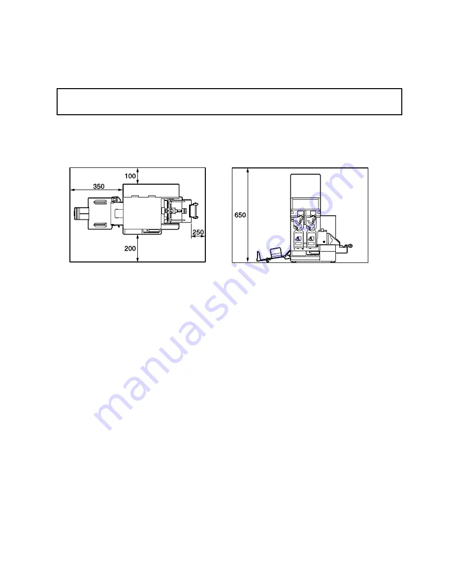
2.  Refer to Safety Precautions in this manual and set up the printer at a proper location.  
 

NOTE

: Secure the space around the printer as follows: (unit: mm) 


3.  Fit the Fan Filter to the printer.  (Refer to Section 2.3, Fitting the Fan Filter.) 
4.  Attach the Media Guide Unit.  (Refer to Section 2.4, Attaching the Media Guide Unit.) 
5.  Attach the Stacker to the printer.  (Refer to Section 2.5, Attaching the Stacker.) 
6.  Connect the printer to a PC with a Centronics Interface Cable.  (Section 2.6, Connecting the 

Printer to Your PC.)  

7.  Insert the Power Cord Plug into an AC outlet.  (Refer to Section 2.7, Connecting the Power Cord.) 
8.  Load the Ribbon.  (Refer to 2.8, Loading the Ribbon.) 
9.  Load the Media.  (Refer to Section 2.9, Loading the Media.) 
10.  Install the Printer Drivers.  (Refer to Section 3, INSTALLING THE PRINTER DRIVERS.) 


CAUTION! 

When moving the printer, be sure to hold the bottom.  Do not hold the operation panel.  

Summary of Contents for CP-1001 SERIES

Page 1: ...Output Solutions Card Printer CP 1001 1002 SERIES Owner s Manual...

Page 2: ...y accessible NOTE This document describes the handling of the CP 1001 series and CP 1002 series card printers The major difference between these two models is that the CP 1001 series includes one prin...

Page 3: ...as this may cause electric shock If the machines share the same outlet with any other electrical appliances that consume large amounts of power the voltage will fluctuate widely each time these applia...

Page 4: ...gh humidity dust or gas Ensure the printer is operated on a stable and level surface Any data stored in the memory of the printer could be lost during a printer fault Try to avoid using this equipment...

Page 5: ...Attaching the Media Guide Unit 2 3 2 5 Attaching the Stacker 2 4 2 6 Connecting the Printer to Your PC 2 6 2 7 Connecting the Power Cord 2 7 2 8 Loading the Ribbon 2 8 2 8 1 Ribbon Loading Procedure...

Page 6: ...of Feed Failure 5 9 APPENDIX SPECIFICATIONS A1 1 A1 1 Printer A1 1 A1 2 Media A1 2 A1 2 1 Media Size A1 2 A1 2 2 Effective Print Area A1 2 A1 3 Ribbon A1 3 CAUTION 1 This manual may not be copied in w...

Page 7: ...le Just put the media stack on the Auto Media Feeder Not only business cards but also post cards etc can be printed Since this printer can be used as a network printer there is no need of an exclusive...

Page 8: ...ase make sure all accessories are supplied with the printer Fan Filter 2 sets Power Cord 1 pc Print Head Cleaner 1 pc Media Guide Unit 1 pc Stacker 1 pc Media Stopper 3 pcs Fixing Screw 1 pc Media Wei...

Page 9: ...002 Series NOTE Since the CP 1002 series is provided with the two print head mechanisms its auto media feeder is protruding from the printer s enclosure causing the larger machine width than the CP 10...

Page 10: ...de Unit Roller Arm Parallel Interface Port Power Inlet Fan Filter Auto Media Feeder Print Head Pinch Roller Platen Print Head Mechanism Ribbon Drive Block Print Head Mechanism No 1 Print Head Mechanis...

Page 11: ...Feed Key Used to feed a piece of media or discharge the media when an error occurred Used to make positioning of media RESTART key Reissue Key Used to exit from the pause mode to restart issuing the...

Page 12: ...s jammed during paper feed Yes 5 NO PAPER m l m The media has run out or the media is not loaded properly Yes 6 NO RIBBON m l m The ribbon has run out Yes 7 HEAD OPEN m l m Feed or printing was attemp...

Page 13: ...ON LINE LED and POWER LED are illuminated 3 Before turning off the printer Power Switch verify that the ON LINE message appears in the LCD Message Display and that the ON LINE LED is on and is not fl...

Page 14: ...fingers or articles of clothing to get caught into any of the moving parts of the printer Make sure to turn off the printer power and to remove the power cord from the printer whenever working on the...

Page 15: ...to Section 2 4 Attaching the Media Guide Unit 5 Attach the Stacker to the printer Refer to Section 2 5 Attaching the Stacker 6 Connect the printer to a PC with a Centronics Interface Cable Section 2 6...

Page 16: ...ws and spread the Media Guides 2 Lift the Media Holder and put it on top of the Media Holder Unit by fitting its stud into the hole NOTES 1 Do not spread the Media Guides by force as this may cause de...

Page 17: ...2 5 Attaching the Stacker 1 Open the Stacker Table 2 Attach the Stacker in front of the Media Outlet by inserting the hooks of the Stacker into the slots in the printer front and then secure the Stack...

Page 18: ...nting long media fold the Stacker Table loosen the Fixing Screw and then pull up the Media Tray 5 After securing the Media Tray with the Fixing Screw open the Stacker Table Place the Media Stoppers ma...

Page 19: ...ronics Interface Cable to the parallel port on the right side of the printer 3 Fix the connector with the clampers 4 Connect the other side of the Centronics Interface Cable to the parallel port of yo...

Page 20: ...into an AC outlet 1 Make sure that the printer Power Switch is turned to the OFF position before connecting the Power Cord to prevent possible electric shock or damage to the printer 2 Use only the P...

Page 21: ...printed on this printer with a laser printer as this will melt the ribbon transferred to the media 4 Be sure to use the ribbon that matches the media width Failure to do this may cause ribbon wrinkle...

Page 22: ...m the Ribbon Module Remove the Ribbon Stoppers from the Ribbon Shafts 4 Insert the Ribbon Shafts into the ribbon cores aligning the tab of the Ribbon Shaft with the notch of the ribbon core 5 Fit the...

Page 23: ...le in place as shown in the figure below 8 Slide the Ribbon Module onto the Print Head Mechanism NOTE Be careful of the orientation of the Ribbon Module 9 Slowly lower the Ribbon Module together with...

Page 24: ...any slack in the ribbon Close the Top Cover NOTE For the CP 1002 series repeat the above procedures to another ribbon module 2 8 2 Removing the Ribbon Module with the Ribbon Loaded 1 Turn the Head Le...

Page 25: ...message 1 Print Head Mechanism No 1 2 Print Head Mechanism No 2 2 When the ribbon ended in the middle of printing the printer prints from unfinished media when the RESTART key is pressed However the n...

Page 26: ...dia is slightly curled bend it in the opposite direction being careful not to wrinkle the media surface 3 Do not use curled wrinkled folded or torn media 2 9 1 Loading the Business Card and Post Card...

Page 27: ...n the above diagram 2 Do not stack the cards exceeding the upper limit line 3 In case of 0 22 mm thick media 300 pieces can be set at the same time As the media becomes thicker the number of media tha...

Page 28: ...a from the Stacker Printed media is stacked on the Stacker Table When removing them move the Knob in the direction of the arrow to slant the Stacker Table After removing the media restore the knob to...

Page 29: ...CPU Pentium 150MHz or more or equivalent in it 2 Operating System Windows 98 Windows 98 Second Edition Windows Me Windows NT Workstation 4 0 Service Pack 3 or greater Windows NT Server 4 0 Service Pa...

Page 30: ...g is the installation procedure for Windows 98 NOTE Before installing the Printer Driver to your PC make sure that the all applications are closed 1 Set the CD ROM into the CD ROM drive 2 Click on the...

Page 31: ...the Browse button Dialogue box will appear 8 Choose the CD ROM drive for the Drives and click on the cp driver folder in the Folders Highlight the cp1002 inf in the File name and click on the OK butto...

Page 32: ...ck on the Next button 12 Choose the LPT1 ECP Printer Port from the available port list and click on the Next button 13 Click on the Finish button NOTES 1 If you want to change the printer name type in...

Page 33: ...the all applications are closed 2 It is necessary to log in Windows NT 4 0 with the authorised user name 1 Set the CD ROM into the CD ROM drive 2 Click on the Start button choose the Settings and the...

Page 34: ...ox will appear 7 Click on the Browse button 8 If the following screen appears click on the Cancel button 9 Choose the CD ROM drive for Look in and the contents of the CD ROM are listed Choose the CP D...

Page 35: ...P 1001 when using the CP 1002 model choose Output Solutions CP 1002 12 Click on the Next button 13 Click on the Next button NOTES 1 If you want to change the printer name type in a new printer name Th...

Page 36: ...e Finish button NOTE Do not print the test page Without proper printer driver settings an error may occur 16 Finally copy the necessary files to the Windows Click on the Start button choose the Settin...

Page 37: ...the Start button choose the Settings and then click on the Printers Double click on Add printer 3 The Add Printer Wizard dialogue box will appear 4 Click on the Next button 5 Choose the Local printer...

Page 38: ...ue box will appear 8 Click on the Browse button 9 Choose the CD ROM drive for Look in and the contents of the CD ROM are listed Choose the CP DRIVER folder Highlight the CP1002 INF and click on the Op...

Page 39: ...CP 1002 12 Click on the Next button 13 Click on the Next button NOTES 1 If you want to change the printer name type in a new printer name This printer name is displayed when selecting the printer on...

Page 40: ...settings an error may occur 16 Click on the Finish button 17 When the following screen appears click on the Yes button to continue 18 Finally copy the necessary files to the Windows Click on the Star...

Page 41: ...he CD ROM drive 2 Click on the Start button choose the Settings and then click on the Printers and Faxes Double click on Add a printer 3 The Add Printer Wizard dialogue box will appear 4 Click on the...

Page 42: ...the Next button 7 Click on the Have Disk button The Install From Disk dialogue box will appear 8 Click on the Browse button 9 Choose the CD ROM drive for Look in and the contents of the CD ROM are li...

Page 43: ...P 1001 when using the CP 1002 model choose Output Solutions CP 1002 12 Click on the Next button 13 Click on the Next button NOTES 1 If you want to change the printer name type in a new printer name Th...

Page 44: ...error may occur 15 Click on the Finish button 16 When the following screen appears click on the Continue Anyway button 17 Finally copy the necessary files to the Windows Click on the Start button cho...

Page 45: ...ing the printer drivers make sure that the all applications are closed 1 Click on the Start button choose the Settings and then click on the Printers Printers and Faxes for Windows XP The Printers scr...

Page 46: ...k 2 To avoid injury be careful not to pinch your fingers while opening or closing the Top Cover and Print Head Block 3 The Print Head becomes very hot immediately after printing Allow it to cool befor...

Page 47: ...with the enclosed Dust Brush Or wipe them with a soft cloth slightly moistened with alcohol 6 After cleaning the Platen Pinch Roller and Feed Rollers reassemble the Plates A B CP 1002 only and C in t...

Page 48: ...rrecting the Skew Print 2 When restoring the Media Guide Unit fit the slit of the Media Guide Unit onto the Shaft of the Auto Media Feeder Refer to Section 2 4 Attaching the Media Guide Unit 5 Remove...

Page 49: ...T key Refer to Section 2 9 Loading the Media EXCESS HEAD TEMP The Print Head is overheated Turn off the printer and allow it to cool down about 3 minutes If this does not solve the problem call the ne...

Page 50: ...Output Solutions service representative The media is not fed 1 The media is not loaded properly 2 The condition of the media is not good Curled wrinkled folded or torn media 3 The media is thin 4 The...

Page 51: ...e printed image is blurred or dirty 1 The Print Head is not clean 2 Output Solutions authorised media is not used 3 The setting of the printer driver is incorrect 4 The media surface is covered with p...

Page 52: ...enclosed Dust Brush or alcohol Refer to Section 4 1 2 Platen Pinch Roller and Feed Rollers 3 Clean the Platen with the enclosed Dust Brush or alcohol Refer to Section 4 1 2 Platen Pinch Roller and Fe...

Page 53: ...he jammed media CP 1002 only 6 Remove the Plate A and get rid of the jammed media NOTE For the CP 1001 series the Plate A and Plate C share the centre stud 7 Remove the Set Screw to detach the Auto Me...

Page 54: ...ken If the ribbon breaks before it has been used up fix it with adhesive tape in the following procedure However it is better to replace it with a new ribbon 1 Open the Top Cover fully 2 Turn the Head...

Page 55: ...upply Roll while another person holds the flat ends of the Ribbon Take up Roll Re roll the ribbon straight onto either roll applying tension to the ribbon NOTE Do not pull the ribbon with excessive te...

Page 56: ...crew by only one or two turns Too many turns may cause the screw to come off 2 Adjust the angle of the Media Guide Unit referring to the scale marked on the Auto Media Feeder Cover 3 When the angle is...

Page 57: ...the enclosed Media Weight onto the Media Holder Shaft NOTE When the Media Weight is not used keep it on top of the Auto Media Feeder Cover by inserting the Media Weight into the slits Media Weight Me...

Page 58: ...1 mm 20 kg AC220 240V 10 15 50 60 Hz 2Hz 1 4 A 240 W maximum 0 08 A 20 W maximum 2 449 mm x 307 mm x 403 mm When the stacker is attached the width will be 754 mm 23 kg Operating temperature range Rela...

Page 59: ...se of 0 22 mm thick media 5 Capacity of the Stacker 300 pieces In case of 0 22 mm thick media A1 2 2 Effective Print Area The figure below illustrates the relation between the head effective print wid...

Page 60: ...mm max Roll Direction Ink side faces outside Material Cardboard Inner Diameter f 25 5 mm 0 5 0 Core Shape Refer to the diagram below Back Treatment Coated Leader Tape Polyester film Opaque 300 mm lon...

Page 61: ...61 E EO1 33042...

Reviews: