background image

OPTIONAL UPGRADES


CONNECTIONS AND INSTALLATION


10


19


OUTBACKGUIDANCE.COM


OUTBACKGUIDANCE.COM


RTK Rover Kit Contents (optional)


Unpack your RTK rover kit and identify the parts as shown. See "Installing the Rover Radio" on page 18 for 
instructions on installing the rover radio.


Installing the Lightbar


The lightbar kit includes suction cup mounting hardware (with mounting ball), a separate mounting ball, and an 
extension cable. Use the separate mounting ball in place of the mounting ball included with the suction cup 
mounting hardware.


   ! 

WARNING:


Do not mount the lightbar in a location where it interferes with seeing other information, controls, 
or the field.


150-0008-000


150-0010-000


Antenna (for 400 MHz rover radio)*


Antenna (for 900 MHz rover radio)*


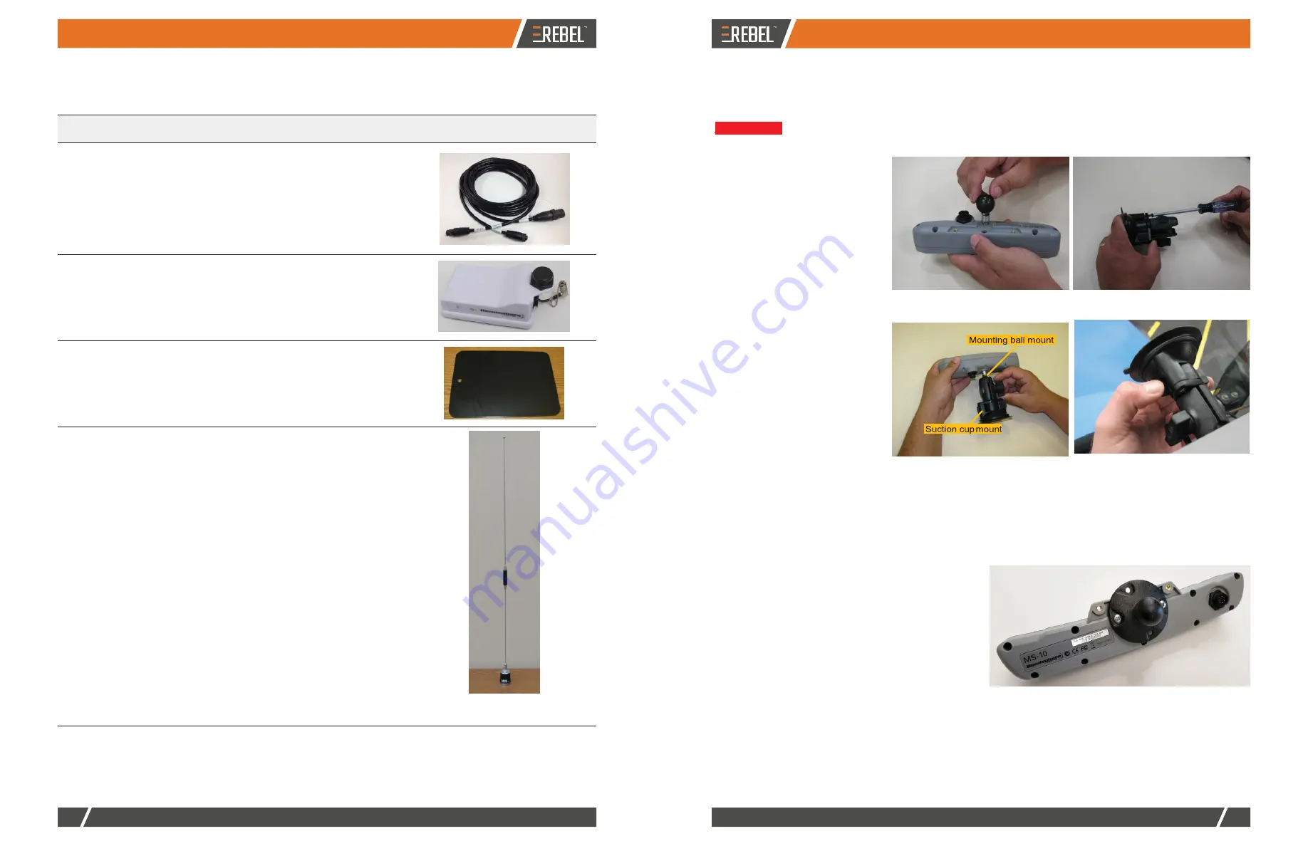
Using the photos at right install the 
suction cup mounting hardware on 
the lightbar then install the lightbar in 
your preferred location.


Before installation, thoroughly clean 
the mounting location (such as the 
inside cab window surface).


1.  Attach the mounting ball to 

the back of the lightbar.


2.  Using the two screws 

included with the suction cup 
hardware, assemble the 
suction cup mount.


3.  Attach the suction cup 

mount to the mounting ball 
on the lightbar then tighten.


4.  Press the vacuum mount to 

the window.


5.  Turn the vacuum cup's twist 

lock counterclockwise to 
create the seal.


6.  Adjust the lightbar to a


Step 1: Attach mounting ball  to lightbar 

Step 2: Assemble suction cup mount


*Your RTK kit will include the antenna that 
matches your rover radio (400 MHz radio 
or 900 MHz radio)


suitable viewing angle.


Step 3: Attach suction cup mount to 

mounting ball and tighten


Steps 4/5: Attach suction cup mount to 

mounting location and tighten


Installing the Switchbox


The switchbox kit includes suction cup mounting 
hardware similar to the lightbar. Using the photo at right 
and the lightbar installation photos above as reference, 
install the switchbox in your preferred location.


802-106 -000#


1


Rover radio (400 MHz)*


802-1075-000#


1


Rover radio (900 MHz)*


*Your RTK kit will include one of the rover 
radios listed above


601-1136


1


Rover radio mounting plate


Part Number


Qty


Description 

Photograph


050-0044-01


1


RTK cable


Connects COM1 cable to antenna and 
rover radio


Summary of Contents for Rebel

Page 1: ...www outbackguidance com Quick Start Guide ...

Page 2: ...PN 875 0412 01 Rev E1 ...

Page 3: ... the installation of your vehicle s REBEL autosteer kit Check package contents Refer to the Kit Contents pages starting on page 2 and if applicable the Optional Upgrades pages starting on page 8 to confirm you have received all parts of your REBEL system The bottoms of the Kit Contents pages are color coded to indicate the kit type Broad Acre Row Crop or Sub Inch We recommend recording your dealer...

Page 4: ...ons replace the Job field buttons 7 You can press Vehicle Profiles to start adding a vehicle or press Implement Profiles to start adding an implement however to learn more about adding vehicles and implements press Skip to close the Start Up Menu then refer to REBEL Help on your terminal see Using Onscreen Help on page 28 REBEL must have a GPS position to begin a job and provide guidance REBEL sta...

Page 5: ...e network you want to connect to the selected network button is green b Press Connect If the network requires no login information unlocked lock to far right of button a spinning progress circle appears to the right of the button you pressed and when connected the lock changes to a green check at right If the network requires a password enter the password in the window that appears then press Done...

Page 6: ...tosteering controller 604 0015 000 1 Terminal mounting hardware Round base attach to terminal Double socket arm mount Bar mount base with U bolts nuts 050 0020 01 1 LAN USB cable Connects LAN USB port on terminal to eDriveXC cable 050 0022 01 1 Power cable Connects power port on terminal to power adapter cable 050 0043 01 1 COM1 cable Connects COM1 port on terminal to switchbox lightbar AC110 cabl...

Page 7: ...ocation where it interferes with seeing other information controls or the field Looking at the screen for too long while operating the vehicle can cause a crash 1 Use the terminal mounting hardware to mount the terminal Review the terminal mounting hardware top photo atright 2 If necessary loosen the knob on the arm mount andremove the ball mounts from the mounting assembly Using the bottom photo ...

Page 8: ... 13 and REBEL Connection Diagrams starting on page 14 as guides connect the power adapter cable to your preferred power source Option 1 Connect to ignition switch Negative Positive Signal Wire Connects COM1 port on terminal to switchbox lightbar AC110 cable and antenna cable the power port on the REBEL terminal 4 Coil excess cable in a protected location then secure the installation with tie strap...

Page 9: ...nector on the retrofit kit to the 4 pin Deutsch connector on the COM2 cable Part Number Qty Description Photograph 050 0041 01 1 COM2 cable Connects COM2 port on terminal to foot switch 050 0045 01 1 Antenna extension cable Connects COM1 cable to antenna 050 0046 01 1 Power adapter cable Connects power cable to power source 720 0033 00A 1 Antenna mount 051 0397 10 1 Adapter Cable 676 0024 000 1 An...

Page 10: ...place of the mounting ball included with this part X at right a Insert the 2 pin weather pack closest to the negative ring terminal into the relay next to thepower posts on the IBBC bracket Apply enough pressure to snap the plug into the relay b Insert the 2 pin weather pack farther from the negative ring terminal into the relay near the IBBC connector on the IBBC bracket Apply enough pressure to ...

Page 11: ...ector part of COM2 cable 4 pinfemale Deutschconnector in tractor cab Foot Switch Kit Contents optional Unpack your foot switch kit and identify the parts as shown See Installing the Foot Switch on page 18 for instructions on installing the foot switch in your preferred location Non ISOBUS Ready Vehicle Connections Non ISOBUS ready vehicles that do not have an IBBC connector on the back of the vehi...

Page 12: ...unting ball to the back of the lightbar 2 Using the two screws included with the suction cup hardware assemble the suction cup mount 3 Attach the suction cup mount to the mounting ball on the lightbar then tighten 4 Press the vacuum mount to the window 5 Turn the vacuum cup s twist lock counterclockwise to create the seal 6 Adjust the lightbar to a Step 1 Attach mounting ball to lightbar Step 2 As...

Page 13: ...ides install the foot switch 1 Connect the foot switch cable of the COM2 cable to the foot switch 2 Install the foot switch in an easily accessible position Installing the Rover Radio Mount the rover radio on top of the vehicle cab to ensure line of sight to the RTK base station The bottom of the rover radio includes a built in magnet for easy placement on the included mounting plate 1 Clean and d...

Page 14: ...e terminal 6 Connect the appropriate cables to the terminal 054 0192 000 1 054 0193 000 1 054 0194 000 1 054 0195 000 1 Power cable 12 ft Short kit Power cable 21 ft Long kit Your kit includes one of the above cables Data relay cable 10 ft Short kit Data relay cable 20 ft Long kit Your kit includes one of the above cables 7 Connect the terminal to the mounting hardware Mounting the Antenna You sho...

Page 15: ...2 port 8 LAN USB port Power port 3 4 6 7 8 9 3 4 Item Description Views COM1 COM2 LAN USB POWER Terminal 752 0005 01 front view ports in rear RS232 COM2 cable 050 0042 01 ISOBUS ISOBUS ISOBUS extension cable 054 0197 000 RUN HOLD ISOBUS to ISOBUS ready implement if COM2 cable does not reach Power cable 054 0192 000 Short kit or 054 0193 000 Long kit IBBC bracket 750 0161 000 To vehicle s battery _...

Page 16: ...CONNECTIONS ANDINSTALLATION CONNECTIONS ANDINSTALLATION 14 15 OUTBACKGUIDANCE COM OUTBACKGUIDANCE COM REBEL Connection Diagrams Connection Diagram 2 With ISOBUS Connection Diagram 1 Without ISOBUS ...

Reviews: