67
Chapter 6
W
elding Condition
F
UNCTION
ON
O
PERATION
P
ANEL
W
ELDING
C
ONDITION
C
HAPTER
6
6.2.2
Setting screen
This section explains the functions of the setting screens displayed on the LCD panel as well as the basic operation
methods.
6.2.2.1
Constructions and switching of setting screen
If the welding power source starts normally, the Home Screen will usually be displayed.
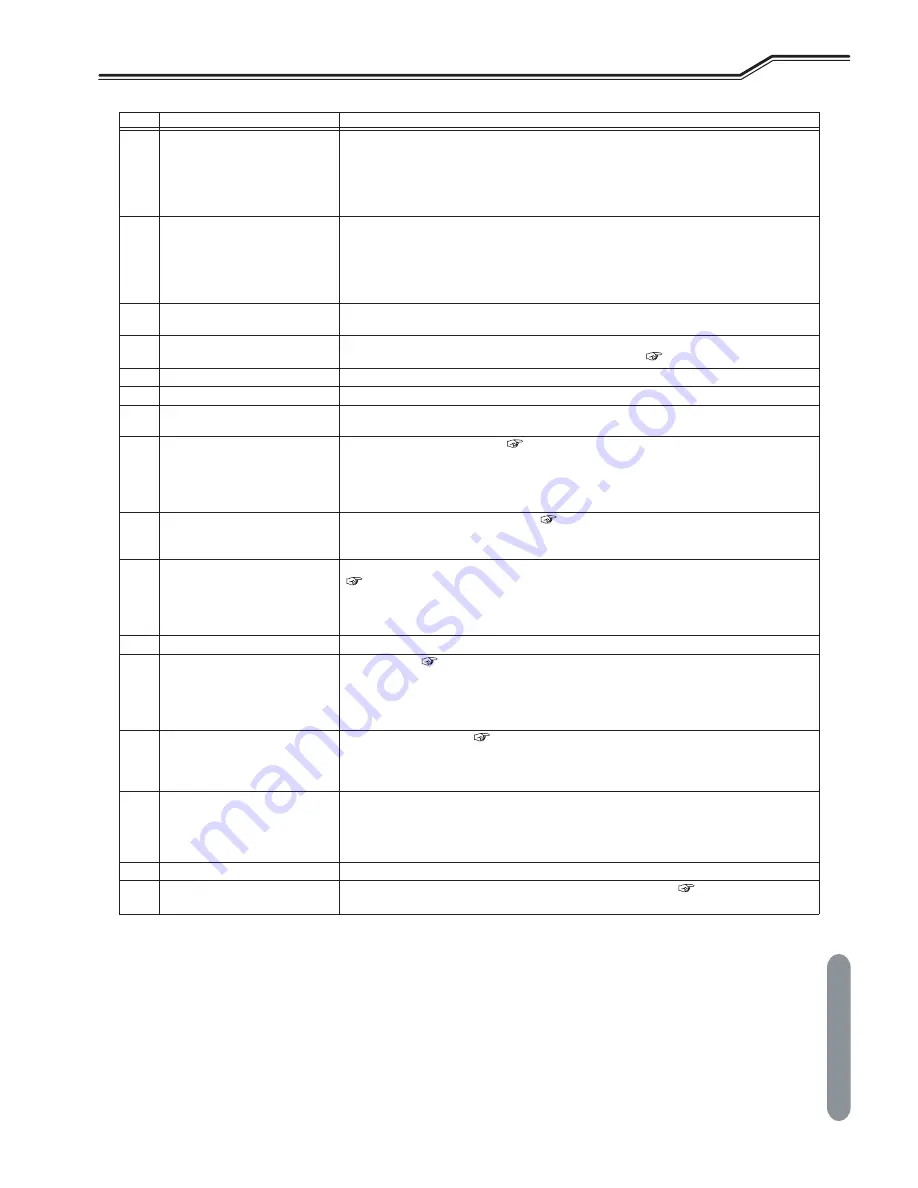
3
Parameter adjustment knob
Pressing this knob switches the digital meter (left/right) that needs to be set.
Turning this knob changes the value of the selected parameter.
Sets the welding current / wire feeder speed when the left digital meter is selected. Switching
between welding current / wire feeder speed is enabled by pressing the UNIT CHANGE key.
Sets the welding voltage when the right digital meter is selected.
If the knob is turned faster, the amount of change will be 10 times larger.
4
UNIT CHANGE key
Switches between welding current / wire feeder speed when the left digital meter is selected.
When the right digital meter is selected and when the SYNERGIC mode is selected as the welding
voltage adjustment method, pressing this key switches the value displayed on the right digital meter
between “fine adjustment value” and “actual voltage value”. (In the SYNERGIC mode, the welding
voltage appropriate for the welding current is regarded as ±0, based on which the welding voltage is
finely adjusted.)
5
DISPLAY SWITCH key
Switches the welding sequence that need to be set. During the welding, the display can be switched
to display the value set as the welding condition.
6
LCD panel
The LCD panel can be used to display the welding conditions that have been set, change the welding
conditions, and make settings for other various types of menu. (
5.3
-
Power ON and Gas Supply)
7
MENU key
Switches between the welding condition setting screens and the MENU screen.
8
CANCEL key
Cancels the operation of various settings and returns to the previous settings.
9
Screen Operation knob
Used for selecting the functions and changing the settings of the setting screens displayed on the
LCD panel.
10
CONSTANT PENETRATION key
Activates the penetration control. (
6.6.9
-
Penetration control adjustment)
Press this key makes the LED lit, and automatically adjusts the wire feed speed so that the welding
current becomes always constant even with the wire feeding length changed.
This function is available only when the "MILD STEEL CORED", "MILD FLUX CORED", "STAINLESS
STEEL SOLID" or "STAINLESS STEEL CORED" is selected by the WIRE MATERIALS menu.
11
ARC CONTROL key
Set the arc characteristics (soft to hard). (
6.6.7
-
Arc characteristics adjustment)
Pressing this key makes the LED lit, enabling to adjust the arc characteristics by the parameter
adjustment knob. The arc characteristic in adjustment is displayed on the right digital meter.
12
WAVE FRQ key
Sets the wave frequency when "DC WAVE PULSE" is selected by the WELDING METHOD menu.
(
6.6.9
-
Adjustment of wave frequency)
Pressing this key makes the LED lit, enabling to adjust the wave frequency by the parameter
adjustment knob.
The set wave frequency is displayed on the left digital meter.
13
EN ratio key
Not used on this model.
14
WIRE INCH key
Feeds the wire. (
5.4
-
Wire Inching)
The LED lights during when the key is pressing, allowing the wire to be fed.
The feeding speed can be adjusted by the parameter adjustment knob.
When the analog remote control (optional) is connected, the speed can be adjusted by the welding
current setting knob.
15
GAS CHECK key
Discharges the shield gas. (
5.3
-
Power ON and Gas Supply)
Pressing this key makes the LED lit, allowing the shield gas to be discharged.
After discharging the gas for approximately 2 minutes automatically stops the discharge.
Pressing this key again lights off the LED, stopping the shield gas discharge.
16
TORCH key
Select air-cooled welding torch or water-cooled welding torch to be used. Switching the mode is
enabled by pressing and holding the key for 3 seconds.
•
When the LED is ON: water-cooled welding torch mode
•
When the LED is OFF: air-cooled welding torch mode
17
Terminals for service use
Terminals for the OTC service use.
18
USB connector
For variety of registered data, writes to or reads from the USB memory. (
Chapter 7
-
Administrator
Functions)
No.
Name
Function


