enabling
innovative
electronics
Ossila Ltd
Copyright © 2009-2015
11
2)
When the measurement is being carried out, the Unit should not be moved or touched as
this can impact on the accuracy of the measurement.
3)
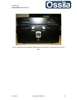
Connect the two coaxial cables connectors to their respective female BNC sockets on the
Multiplexer Measurement Unit back panel, see figure 1. Channel A is the Gate channel, while
Channel B is the Drain. Plug the I/O Connector located at the other ends of the coaxial cable
to the SMU channel A and B connectors located on the back panel. The SMU channel A is the
GATE source, while Channel B is the DRAIN source. Be careful to plug the connectors
correctly, take advantage of the labels at both ends of the cables to double-check the
connections.
4)
Use the USB cable provided to connect the Multiplexer Measurement Unit with the
computer case. To do this, plug the Standard B USB plug to the Standard B USB receptacle
located on the back panel of the Unit, see figure 1. Plug the Standard A USB end of this cable
to any USB 2.0 (or higher) socket on the computer casing. The USB socket must be capable
of delivering enough current to switch the multiplexor channels ON/OFF (500 mA).
Note:
The USB ports on the back of the desktop computer can usually supply more electrical
power that the ones located on the front.
5)
The Ossila Multiplexer Measurement Unit comes supplied with an earth plug; this does not
supply power to the unit. Its use is advised in case your electrical installation is not equipped
with Residual Current Devices (RCD). The earth plug is a safety precaution and should not
affect the quality of the measurement.

