enabling
innovative
electronics
Ossila Ltd
Copyright © 2009-2015
52
Application settings: SMU settings
PLC
(Power Line Cycle) specifies frequency of the electric power
grid(50 or 60 Hz). Keithley 26XX series automatically detects the PLC
of the power supply grid.
Power Line Cycle is the oscillation frequency of the AC current supplied to the end-users through the
electrical power grid. In the EU, Australia, part of Japan and several other countries, the PLC is 50 Hz
with a voltage range of 220-240 V. In USA, Canada and Taiwan, part of Japan, etc the PLC is 60 Hz
with a voltage range of 100-120 V.
Note:
Providing the correct PLC is detected/set, SMUs are usually equipped with built-in filter
capable of rejecting the noise originated from the oscillatory behaviour of the power supply. This
SMU capability is often referred to as PLC noise rejection.
Sample to Avg
specifies the number of current readings that the SMU requires to output a single
measurement point.
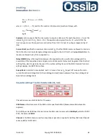
For example, if
Sample to Avg
is set to
N
, the SMU takes
N
independent measurements, which are
then averaged so that a single (averaged) output is returned. Increasing
N
will increase accuracy at
the cost of measurement speed.
N
=1 is usually adequate unless stringent accuracy requirements, or
specific measurement needs, require larger data sample. Refer to the SMU user manual for the
maximum number of sample to average supported by the SMU.
Aperture Time
sets the duration of a single current (or voltage) reading. Aperture Time is expressed
in unit of PLC. The actual value of Aperture Time therefore depends on the PLC frequency, as
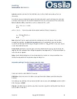
detailed in the following table where Aperture Time is expressed in term of PLC units and seconds.
Aperture Time
PLC
PLC Input
60 Hz
50 Hz
8
8
133 ms
160 ms
4
4
66.6 ms
80.0 ms
2
2
33.3 ms
40.0 ms
1
1
16.6 ms
20.0 ms
1/2
0.5
8.33 ms
10.0 ms
1/4
0.25
4.16 ms
5.00 ms
1/8
0.125
133 ms
2.50 ms
1/16
0.0625
1.04 ms
1.25 ms
1/32
0.031250
520 µs
625 µs
1/64
0.015625
260 µs
312 µs
As for sample to average, longer aperture time increases accuracy by slowing down the acquisition
rate.
Application settings: Measurement: Advanced settings
TC: Initial Delay Time
is the extra settling time the GATE
SMU waits after applying the target voltage when acquiring
TC curves, see diagram in figure 21.
TC: Initial Delay Time
is applied only for the first sweep data


