enabling
innovative
electronics
Ossila Ltd
Copyright © 2009-2015
101
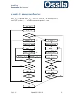
Appendix VI - Measurement Flowchart
CC:
I
DS, i
(
V
DS, i
) and gate leakage
I
GS, i
(
V
DS, i
) with
i
=1, 2,...
N
for
j
=1, 2...
M
gate voltage sweep.
TC:
I
DS, k
(
V
GS, k
) with
k
=1, 2,...
L
for linear and saturation regime
V
DS,r
,
r
= 1, 2.
j
=0
NO
Yes
Yes
NO
Yes
Yes
NO
Yes
NO
Yes
NO
TC?
Next FET?
device
i
>
N
?
j
>
M
?
Log CC data
STOP
j
=0
CC: Apply
V
GS,j
Wait
t
=Gate Delay
Apply
V
DS,i
Wait
t
=Drain Delay
j
=
j
+1
i
=
i
+1
Multiplexer
Initialisation
CC?
Yes
Acquire
I
DS,i
(
V
DS,i
)
Acquire
I
GS,i
(
V
DS,i
)
r
=0
k
=0
NO
Apply
V
GS.k
TC: Apply
V
DS,r
Wait
t
=Drain Delay
Wait
t
=Gate Delay
Acquire
I
DS,k
(
V
GS,k
)
k
=k+1
k
>
L
?
r
=
2
?
Yes
Log TC data
Next FET?
device

