background image

39

4

Rotation Correction

Use the rotation correction to distinguish the shape of a work by correcting 

its rotating angle even if a work rotates during detection.

Registration of the Color and Pattern for the Rotation Correction

In order to execute the rotation correction, you must register a color 

different from the color for the position & magnification correction. 

Register the color and pattern for the rotation correction from the teaching 

menu in the following procedures.

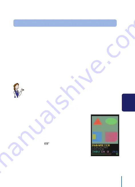
Here explained is the method to register the quadrangle at the lower right 

in the screen as the color and pattern for the rotation correction.

Always register a color of the same size out of the colors not 

included in the background for the rotation correction just as 

done with the color for the position & magnification correction.

Registering a color other than white, gray, and black, will 
make the recognition more stable even when the brightness 

changes. Stabilize even when brightness changes. 

However, select a color at a position apart as much as 
possible since the error at the rotation correction is greater 
when the color for the position & magnification correction is 

close to the center position.

1

  Before registering the color for the 

rotation correction, register the 
color and pattern for the position & 
magnification correction, referring 

to “Position & Magnification 
Correction”. (

See Page 22.)

USE OF APPLIED FUNCTIONS

Ramco Innovations

www.optex-ramco.com

phone 800-280-6933

Summary of Contents for CVS2

Page 1: ...y on LCD Screen Distinction by Patterns Recognition Use of Applied Functions Changing Set Value Troubleshooting Appendix C O L O R V I S I O N S E N S O R S E R I E S Patterns Recognition Sensor Instr...

Page 2: ...you and other persons as well as the damage to the property Symbols and their meanings are as follows Before reading this manual fully understand the meanings of these symbols Indicates a possible ha...

Page 3: ...nction of the device Do not mount the device at any one of the following places to use this product properly and safely If not observed it may cause a fire an electric shock or a failure Place at high...

Page 4: ...device failure Securely mount this device This device may fall off due to insufficient mounting or unstable mounting position resulting in personal injury or an accident Wipe off the dirt on this devi...

Page 5: ...RECOGNITION 16 Outline of Patterns Recognition 16 Registration of Work Pattern Shape 17 Confirming Identity by Switching Display Mode 19 Operation Check by Shifting Work 21 4 USE OF APPLIED FUNCTIONS...

Page 6: ...tside Dimensions Drawing 66 I O Circuit Diagrams 67 Relation between External Input and Bank No 68 External Teaching Timing 68 Function of Auxiliary Output 69 Operation Check by Using Sample Work 70 R...

Page 7: ...s and the detection result taken by the built in camera Also displays each set item and set value See Display on LCD Screen on Page 12 Power Signal Cable Connector Connects the power signal cable See...

Page 8: ...essful by changing the setting even if a detected image is displayed as shown in the right figure See Changing Set Value on Page 48 Tilt the sensor by 10 40 to avoid the mirror reflection when a work...

Page 9: ...very fast is going to be detected the shutter time brightness has to be shortened In such a case make the distance between the sensor and a work closer or add additional external lighting since quanti...

Page 10: ...ge Black Bank switch 0 input 4 Yellow Black Bank switch 1 input 5 Pink Bank switch 2 input External teach input 6 Purple Bank switch 3 input Synchronous input 7 Black Judgment output 8 Red Black Aux o...

Page 11: ...le result is not obtained due to insufficient lighting CVS C3S ExtensionCable 3 m Extension cable for the remote monitor Four cables can be connected at maximum for extension 15 m in total CVS C2C PC...

Page 12: ...eration Main Menu 1 Press or to select an intended item on the main menu The selected item is displayed in yellow PARAMETER Displays the Set Value Reference screen TEACHING Displays the Teaching Menu...

Page 13: ...ALUE on Page 48 Teaching Menu Performs the patterns recognition the position magnification correction the registration of a pattern shape for rotation correction and the edition of the masking area or...

Page 14: ...d value can be changed by the CMPLEVEL set value Bank number Displays the present bank number 0 14 Auxiliary output status Displays ON OFF condition of an auxiliary output signal Output is ON when is...

Page 15: ...rease a set value etc or change a set item SET button Use to change or edit a set value or move to the selected menu EXIT button Use to change or edit a set value or return to the previous menu VIEW b...

Page 16: ...using the sample work at the end of this manual Use the applied functions such as correction etc if successful distinction cannot be made by this method See USE OF APPLIED FUNCTIONS on Page 22 Outlin...

Page 17: ...and detect Sample See Operation Check by Using Sample Work on Page 70 2 Press and select TEACHING TEACHING is displayed in yellow 3 Press The teaching menu appears SAVE PATTERN is directly executed b...

Page 18: ...6 SAVE PATTERN is displayed in red Registration of the pattern is complete when SAVE PATTERN changes into yellow The patterns recognition without any correction starts operating by the above operation...

Page 19: ...correction This is the screen on the shipment from our factory Displays the image screen before color correction and brightness irregularity correction This is the real image screen COLR Color TRNS T...

Page 20: ...paring TRNS with PTRN Green High identity zone Yellow Middle identity zone Red Low identity zone In case of the above screen of COMP a work is displayed in green and it shows that identity is very hig...

Page 21: ...nfirm whether or not its identity changes 1 Shift the sample work to the lower left in the standard screen Identity has decreased from 100 to 58 Middle identity zone has increased since the work has s...

Page 22: ...ister the color and the pattern for the position magnification correction from the teaching menu in the following procedures Here the method to register a triangle at the upper left in the screen as t...

Page 23: ...ges to the teaching menu 4 Select STD TEACH by pressing or several times STD TEACH is displayed in yellow 5 Press for 3 seconds or more STD TEACH is executed and the display changes to the color selec...

Page 24: ...hows that no detection color is registered A function item of the color selection menu is displayed Pressing will display the next function while pressing will display the previous function Other than...

Page 25: ...ion window to the left as far as the center of the triangle by holding pressed If the color detection window moves to the left too much move it to the right by pressing By pressing imaging stops and t...

Page 26: ...eturn to the teaching menu without completing the registration If not performing the position magnification correction cancel the registration for the correction For this operation set the color displ...

Page 27: ...level even when the work actually being imaged is shifted 1 Display the teaching menu and confirm that the output is ON with the identity is 100 Confirm identity frequency becomes 100 2 Press The stan...

Page 28: ...played By the initial setting the portions other than the central part are masked shown in blue In this case only the central part in the screen can be compared In such a case widen the comparison tar...

Page 29: ...in the screen the target zone by editing the masking zone is explained below as an example The following two methods are available to select the masking zone Method to select the zone occupied by the...

Page 30: ...he applied function used last time is reflected The function item of the mask edition menu is displayed Pressing will display the next function while pressing will display the previous function Other...

Page 31: ...ing window to the height a bit higher than that of the triangle by pressing If the height of the masking window gets too high reduce it by pressing 7 Display LARGE SIZE by pressing USE OF APPLIED FUNC...

Page 32: ...ay MASK WINDOW by pressing 4 times MASK WINDOW is a function to add or delete this masking window zone shown by red translucent portion to or from the mask zone Mask zone blue portion 10 When is press...

Page 33: ...s deleted from the mask zone 13 Press for 3 seconds or more if the mask zone is appropriate The teaching menu is restored If you want to restore the former mask zone when the mask area is deleted by m...

Page 34: ...ete 1 Display the teaching menu and confirm that the identity is remains high 2 Press The standard screen is restored Identity remains high even when the work position is shifted 3 Display COMP by pre...

Page 35: ...In such a case register another color for the rotation correction Then the patterns can be compared by correcting the rotating angle even when a work rotates See Rotation Correction Page 39 for detai...

Page 36: ...ress The teaching menu is displayed 3 Select COLOR WINDOW by pressing or COLOR WINDOW is displayed in yellow Area outside color detection area Red translucent portion Color detection area Area outside...

Page 37: ...ng will move it downward 7 Display RIGHT MOVE by pressing 8 Every pressing will move the color detection area to the right while every pressing will move it to the left 9 Display LARGE SIZE by pressin...

Page 38: ...isplayed inside the window by pressing 13 Press for 3 seconds or more if the color detection area is appropriate The teaching menu is restored When is pressed for 3 seconds or more the former color de...

Page 39: ...register a color of the same size out of the colors not included in the background for the rotation correction just as done with the color for the position magnification correction Registering a colo...

Page 40: ...yed 4 Select ROTATION by pressing or ROTATION is displayed in yellow 5 Press for 3 seconds or more ROTATION is executed and the color selection menu is displayed The operating method on the color sele...

Page 41: ...window size a function to change the color range is also available See Function of Color Selection Mask Edition Menu Page 58 for details of the function The color in the color detection window is dis...

Page 42: ...ill stop imaging and a still picture will be displayed in the screen allowing easier operation Pressing again will restart imaging 10 The following screens are displayed alternately when the color det...

Page 43: ...If some masking zone is registered referring to Masking See Page 29 the setting can be used as is if the position of a work is not changed The registration of the color and pattern for the rotation co...

Page 44: ...es Confirm that both the colors are displayed 4 Rotate the sample work in the standard screen Identity remains high 5 Display THRU by pressing 4 times Color for rotation correction Color for position...

Page 45: ...by pressing twice The reason when the low identity portion in red has increased is because imaging error occurs with the near side shifted from the far side when a work is imaged obliquely The triangl...

Page 46: ...YSTEM is displayed in yellow 2 Press The system menu is displayed 3 Confirm that BRIGHT CMPENST is displayed in yellow If not press or several times 4 Press for 3 seconds or more BRIGHT CMPENST is exe...

Page 47: ...nge remaining in red it is at the upper limit of the shutter time In such a case get this device closer to the work or increase the image sensor gain IMG GAIN 7 If no irregularity is found in the scre...

Page 48: ...es 2 Press Then the set value reference screen is displayed Set item Set value 3 Display an intended set item whose data to be changed by pressing or PURPLE Independent set item for each bank YELLOW S...

Page 49: ...een is restored Pressing will restore the set value reference screen canceling the revision to the set value 7 Press The standard screen is restored Initializing Set Value Initializing Set Value 1 Cha...

Page 50: ...position correction in the vertical direction 1 Register a pattern involving the position magnification correction using the sample work attached at the end of this manual See Page 70 in advance See P...

Page 51: ...et value is displayed in red 7 Decrease the set value by pressing POSIT X 5 The work in orange returns to the right since the maximum value for the horizontal position correction is limited to 5 pixel...

Page 52: ...he difference in color against the registered pattern 0 brings the highest sensitivity and slight difference in color can be distinguished Range of detection color for position correction 1 COLOR P 0...

Page 53: ...one of colors is registered Horizontal position correction tolerance 1 POSIT X 0 208 104 Sets the tolerance of the horizontal position correction Corrects up to the set value pixels When set to 0 no...

Page 54: ...egularity correction BRIGHT COMPENST and PC communication PC LOAD SAVE 0 Permits teaching on all items 1 Prohibits the screen registration SAVE PATTERN only 2 Prohibits teaching on all items Synchroni...

Page 55: ...reverse OUTSIDE 0 1 0 0 Turns ON output when identity is above the threshold value and turns OFF output when identity is below the threshold value 1 Turns OFF output when identity is above the thresh...

Page 56: ...d screens brightness irregularity data are initialized 10 All set values will be locked 11 Locked condition of all set values is released Communication setting COMMUNIC 0 5 0 Sets communication functi...

Page 57: ...fective output Turns OFF by the bank switch and turns ON by the first judgment output after bank switch Turns OFF after the first imaging is complete after powered ON 1 Judgment timing output Every ti...

Page 58: ...elected by teaching As the set value increases wider range of colors is covered Darkness correction ratio 1 DARK CMP 0 25 27 Sets the ratio to correct the darkness of colors No correction is made with...

Page 59: ...AIN Image sensor gain and add the external lighting or make the distance to the work closer If the set value of DARK CMP Darkness correction ratio is too large a dark color cannot be detected When a d...

Page 60: ...correction or Rotation correction is not done The set value of MAGNIFY Magnification correction allowable ratio POSIT X Horizontal position correction allowable ratio POSIT Y Vertical position correc...

Page 61: ...l speed m s Horizontal width of imaging area 10 4 e g When shutter time set value 135 Work travel speed 0 7 Horizontal width of imaging area 30 Number of pixels causing blur 32 76 Shape deforms when m...

Page 62: ...he image screen When the installation condition of the sensor has changed after the brightness irregularity correction was executed under the other installation condition the brightness irregularity c...

Page 63: ...shold value The external lighting does not turn ON correctly COMMUNIC Communication setting may be set to 1 to 5 Set to 0 When COMMUNIC Communication setting is set at 1 to 5 the external lighting con...

Page 64: ...not displayed The set value of SYNCHRON Synchronization input may be set at 0 to 3 When the set value of SYNCHRON is 0 to 3 the window is not displayed when image is not being taken This is because t...

Page 65: ...5 2 11 9 8 4 5 0ms at Double speed resolution Output 4 NPN PNP O C Max 100 mA Residual voltage 10V or less Input Bank switch input External teaching 4 points Ambient working temperature 0 40 C Ambient...

Page 66: ...66 Outside Dimensions Drawing 42 0 95 0 33 8 87 0 2 4 3 4 2 4 0 11 0 21 0 28 2 Unit mm Ramco Innovations www optex ramco com phone 800 280 6933...

Page 67: ...ck Aux output Red Black Internal Circuit Protection diode 12 24 VDC Brown 0 V Blue CVS2 P10 P20 P40 PNP I O Input circuit Bank switch 0 Bank switch 3 Photocoupler Internal Circuit Bank switch 0 input...

Page 68: ...F 1 ON OFF OFF OFF 2 OFF ON OFF OFF 3 ON ON OFF OFF 4 OFF OFF ON OFF 5 ON OFF ON OFF 6 OFF ON ON OFF 7 ON ON ON OFF 8 OFF OFF OFF ON 9 ON OFF OFF ON 10 OFF ON OFF ON 11 ON ON OFF ON 12 OFF OFF ON ON 1...

Page 69: ...rnal operation Aux output Pixel reset Imaging Compare Pixel reset Imaging Compare AUXOUT 2 Lighting output Application Used when turning ON a light other than exclusive external light CVS LW1 only whe...

Page 70: ...e Work Two kinds of sample works are prepared Teach this illustration and use it for the registration of colors and patterns or the confirmation of set values etc Sample Sample Ramco Innovations www o...

Page 71: ...to acts of God The warranty stated herein shall cover only the delivered manufacturer s sole product The damages that have caused by the failure of the delivered manufacturer s product shall not be c...

Reviews: