


5.2 Water Discharge Test
Before the test, make sure that the water discharge pipeline is
smooth, and check that each connection is sealed properly.
Conduct the water discharge test in a new room before the
ceiling is paved.
2. Connect the power supply, and set the air conditioner to operate in
cooling mode. Check the sound of the drain pump, and check
whether the drainage outlet is discharging water properly (based on
the length of the pipe, the discharge may occur 1 minute), and check
for water leakage at each joint.
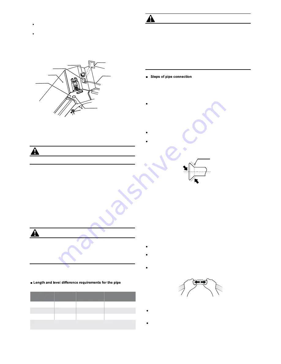
To water suction pipe
Test water outlet
Unit
Drainage pan
Water cover assembly
Water injection pipe
Water discharge trench
Faults, if any, need to be rectified in time.
The drainage plug at the bottom of the unit is used to discharge
accumulated water from the drainage pan when the air
conditioner malfunctions. When the air conditioner is operating
normally, make sure the drainage plug is properly plugged to
prevent water leakage.
3. Stop the air conditioner. Wait for three minutes, and then check if
there is anything unusual. If the water discharge piping layout is not
correct, the excessive water flow will cause the alarm indicator on the
control box to flicker. There may even be water overflowing from the
drainage pan.
4. Continue to add water until the alarm for excessive water levels is
triggered. Check if the drain pump drains water immediately. After
three minutes, if the water level does not fall below the warning level,
the unit will shut down. At this time, you need to turn off the power
supply, and drain away the accumulated water before you can start
up the unit normally.
5. Turn off the power supply, remove the water, and put the water
cover assembly back to the original place.
1. Remove the water cover assembly to connect to the test water
outlet, and use the water injection pipe to inject 2000 ml of water into
the drainage pan.
Measure the required length of the connecting pipe. Make the
connecting pipe using the following method (see the column Pipe
Connection for details).
1. Connect the IDUs before the ODU.
Bend and arrange pipes carefully without damaging the pipes
and their insulating layers.
Before tightening the flare nut, apply refrigerant oil on the outer
surface at the pipe flaring position and the conical surface of the
connecting nut (the refrigerant oil used must be compatible with
the refrigerant of this model), and screw it 3 to 4 turns with your
hand to tighten it as shown in the Fig 3-9.
When connecting or removing a pipe, use two wrenches at the
same time.
Do not put the weight of the connecting pipe on the connector of
the IDU. Otherwise, the heavy weight will deform the connector
and affect the cooling (heating) effect.
Do not bend a pipe more than 90 degrees (see the figure on the
right).
The bend should be as close as possible to the center of the
tube and the bend radius should not be less than 3.5D (pipe
diameter).
Do not bend the flexible tube back and forth more than 3 times.
When bending a pipe, cut off the required recess in the
insulation pipe at the bend and expose the pipe (wrap the bend
with a binding tie after bending).
Keep the elbow radius as much as possible to prevent flattening
or crushing. Use a pipe bender to make tight elbows.
2. The check valve of the ODU should be completely closed (e.g.
the ex-factory condition).
3. After the refrigerant pipe is connected to the IDU and ODU,
discharge the air according to the column Air Discharge. After the
air is discharged, tighten the service nut.
Precautions for flexible pipes:
Bend a thin-walled connecting pipe (see the right figure):
Unscrew nuts from the check valve in each connection, and
connect the flared tube immediately (within 5 minutes). When the
nut at the check valve is removed and placed for too long, dust
and other sundries may enter the pipeline system and cause
failures at a later time.
Fig 3-9
Apply refrigerant oil
Bend the pipe with your thumbs
connections of IDU and ODU
5.3 Connection of Connecting Pipe
Do not let air, dust, or other particles invade the pipeline system
during installation of the connecting pipes.
Install the connecting pipes only when the indoor and outdoor
units are secured.
Make sure to keep the connecting pipes dry during installation
so that no water will enter the piping system.
Connecting copper pipes must be wrapped with insulation
materials (thicker than 10mm, the thickness should be increased
if the unit is installed in a closed humid place).
CAUTION
Maximum
length (m)
Maximum level
difference (m)
Maximum number
of bends
Notes: If the height difference is greater than the allowed level
difference, it is recommended to place ODU above the IDU.
20
15
15
Product
Model
53/71
30
20
15
90/105/120
50
25
15
140/160
CAUTION
CAUTION
9