DMTA-10040-01EN, Rev. E, February 2018
Appendix A
340
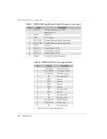
6
AOUT_6
Analog Output 6 (
−
5 V to +5 V)
Meaning: Mix Y
7
GND
Ground
8
VDD
+5 V voltage
9
ENCD_INT
Encoder Interrupt (future expansion)
10
ENCD_DIR
Encoder Direction (future expansion)
11
GND
Ground
12
HW_IO_1
Alarm Output 1 (TTL)
13
HW_IO_2
Alarm Output 2 (TTL)
14
HW_IO_3
Alarm Output 3 (TTL)
15
Unused
Unused (for future expansion)
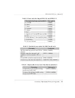
Table 10 NORTEC 600 VGA 15
‑
pin port output
a
a.
Standard VGA output configuration
Pin
Signal
Description
1
VGA_RED
VGA red output
2
VGA_GREEN
VGA green output
3
VGA_BLUE
VGA blue output
4
NC
Not connected
5
GND
Ground
6
GND
Ground
7
GND
Ground
8
GND
Ground
9
NC
Not connected
10
GND
Ground
11
NC
Not connected
12
NC
Not connected
13
LCD_HSYNC
Horizontal sync.
14
LCD_VSYNC
Vertical sync.
15
NC
Not connected
Table 9 NORTEC 600 Input/Output 15
‑
pin I/O connector
(continued)
Pin
Signal
Description
Summary of Contents for nortec 600
Page 8: ...DMTA 10040 01EN Rev E February 2018 Table of Contents viii...
Page 16: ...DMTA 10040 01EN Rev E February 2018 Labels and Symbols 6...
Page 30: ...DMTA 10040 01EN Rev E February 2018 Introduction 20...
Page 58: ...DMTA 10040 01EN Rev E February 2018 Chapter 1 48...
Page 71: ...DMTA 10040 01EN Rev E February 2018 Software User Interface 61 Press the Return key to exit...
Page 72: ...DMTA 10040 01EN Rev E February 2018 Chapter 2 62...
Page 342: ...DMTA 10040 01EN Rev E February 2018 Chapter 7 332...
Page 356: ...DMTA 10040 01EN Rev E February 2018 Appendix B 346...
Page 366: ...DMTA 10040 01EN Rev E February 2018 List of Figures 356...
Page 368: ...DMTA 10040 01EN Rev E February 2018 List of Tables 358...


