background image

IPLEX GAir

1.

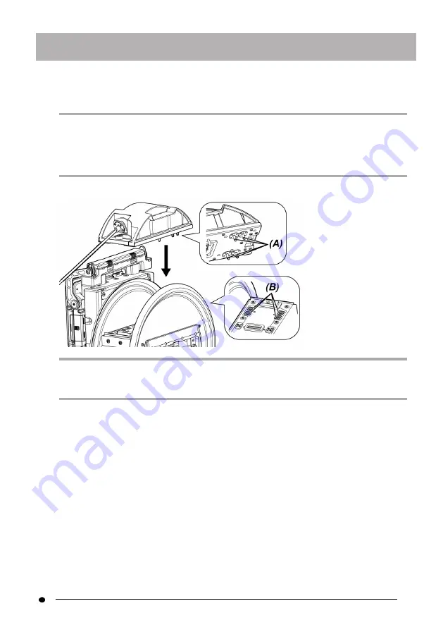
Make sure that no foreign objects such as dirt or dust, etc. are attached to the
terminals of the drum unit and the scope unit.

NOTE:

Check that there is no scratch or damage on the O-rings (4 positions)

(A)

of the terminal on

the scope unit side. If any abnormality occurs on the O-ring, replace it with the O-ring (with
grease) provided with the scope unit. Otherwise, the angulation performance may be
degraded.

2.

Attach the scope unit to the drum unit.

NOTE:

Check the orientation to attach the scope unit according to the air supply connector
positions (4 positions)

(B)

.

41

Summary of Contents for IPLEX GAir IV9000GA

Page 1: ...Industrial Endoscope Issued in September 2021 INSTRUCTIONS IPLEX GAir INDUSTRIAL ENDOSCOPE IV9000GA IV98200GA IV98300GA MM3868 04 ...

Page 2: ......

Page 3: ...dapter nomenclature 26 2 3 LCD monitor nomenclature 27 3 Pre operation preparation and inspection 37 3 1 Transporting the case 37 3 2 Preparing the product 38 3 2 1 Removing the units from the carrying case 38 3 2 2 Removing the scope unit from the scope case 40 3 2 3 Attaching the scope unit 40 3 2 4 Attaching and removing the relay cable 42 3 2 5 Attaching and removing the base unit 45 3 3 Prepa...

Page 4: ...e inspection object 80 4 6 Adjusting the display of the live image 83 4 6 1 Still image Freeze 83 4 6 2 Enlarging the image Zoom 83 4 6 3 Adjusting the brightness 83 4 7 Switching the folder on the live screen 84 4 8 Recording images 85 4 8 1 Preparation for recording images 85 4 8 2 Recording the still image 87 4 8 3 Recording the movie 89 4 8 4 Adding the movie 90 4 9 Playing back the image 90 4...

Page 5: ...or freeze screen 106 5 2 1 Initial setting menu 106 5 2 2 Inputting a title 112 5 2 3 Registering a text string as a preset title 114 5 2 4 Adjusting the image sharpness 115 5 2 5 Adjusting the image color 115 5 2 6 DATE and TIME 116 5 2 7 LANGUAGE 116 5 3 Using the thumbnail screen or the view screen 116 5 3 1 File folder operation menu 116 6 Measurement functions 119 6 1 Scaler measurement funct...

Page 6: ... units 133 9 4 Removing water from the drain 133 9 5 Replacing the fuse 135 9 6 Storing in the case 136 9 6 1 Storing in the carrying case 136 9 6 2 Storing the scope unit in the scope case 138 10 Specifications 141 10 1 Operating environment 141 10 2 Storage environment 142 10 3 Other specifications 142 10 3 1 Other specifications 142 10 3 2 External application standard 146 10 3 3 Software licen...

Page 7: ...ment in a safe place If you have any questions about any information in this instruction manual please contact Olympus The symbols used in the texts of this manual have following meanings indicates the words on the user interface of the product displayed in English indicates the words on the user interface of the product and the language displayed is selectable by user settings Product configurati...

Page 8: ...tial material damage It may also be used to alert against unsafe practices or potential material damage NOTE Indicates a potential situation which if not avoided may result in failure of this instrument TIP Indicates additional helpful information Safety precautions General safety precautions Comply strictly with the precautions described below when handling this instrument The information is supp...

Page 9: ...attery and or the external battery Leaving the battery and or the external battery loaded during storage causes it to be hot which may cause fire The gas tube must not be used for grounding Otherwise it may cause an explosion CAUTION Do not use the instrument in any environment including strongly radioactive environments other than the specified operating environment Using the instrument even in w...

Page 10: ... and EMC performance of the product cannot be assured Do not use the power cord specified for this instrument for other products Do not use the AC adapter outdoors Otherwise electric shock smoke or fire may occur which may cause damage to the instrument The AC adapter is designed for indoor use Do not apply a strong impact to the AC adapter by hitting it against the wall or dropping it to the floo...

Page 11: ...ses and the precision components which constitute the distal end and the angulation section may be damaged Always attach the optical adapter before using this instrument If you use the instrument without attaching the optical adapter to the insertion tube parts screws etc are easily deformed due to contact with hard objects etc If the insertion tube parts are deformed the optical adapter cannot be...

Page 12: ...e optical adapter or the guide head firmly again according to Attaching and removing the optical adapter page 54 or Attaching and removing the guide head page 57 If you sense any abnormality while performing the angulation operation do not attempt to force the angulation operation Otherwise the insertion tube or the inspection object may be damaged Do not allow metal or other foreign objects to en...

Page 13: ...y or AC adapter while accessing to the SDHC card or the microSDHC card Otherwise the recorded data may be damaged Do not remove the SDHC card or the microSDHC card while recording or replaying the image Otherwise recorded data SDHC card or microSDHC card may be damaged Do not repeat inserting or removing the SDHC card or the microSDHC card continuously Otherwise recorded data SDHC card or microSDH...

Page 14: ...e range The continued use may damage or deteriorate the performance of the instrument Do not use the instrument if the contaminants are attached to the outer surface of the instrument The instrument may be damaged or the performance may be deteriorated Do not cover the product with a plastic bag or other objects The inside of the instrument may not be cooled down sufficiently which may damage the ...

Page 15: ...n Bundle the cable of the remote control unit with the cable tie as shown in the picture below When bundling the cable of the remote control unit do not wrap the cable around the remote control unit The excess force may be applied to the cable and it may be damaged Note the following precautions when using the guide head l Never use the guide head if any of its parts are loose The loose parts may ...

Page 16: ...nside the pipe with protrusions or the curved pipe where the centering device cannot be inserted l Location where you feel too tight to insert the insertion tube l Keeping in mind that the insertion tube should be pulled out later do not insert it forcibly If you insert the insertion tube forcibly the insertion tube may not be pulled out l If you feel that something is caught while pulling out the...

Page 17: ... the battery in the specified recharging time stop attempting to recharge the battery Do not allow the battery compartment to become deformed and never put any foreign object into it Do not allow metal or water or any other fluid to get into the battery compartment or onto the battery terminals If any foreign object enters the drum unit remove the battery and disconnect the AC adapter and immediat...

Page 18: ...tery in the following locations l Environments exposed to water high temperature high humidity low humidity and dust l Locations exposed to direct sunlight or radiation l Locations exposed to gas containing halide 1 1 The performance of some electrical parts may deteriorate due to the halide in insecticides pesticides and gaseous extinguishing agents etc Do not use charge or store the battery in a...

Page 19: ...batteries contact Olympus Comply strictly with the precautions described below when handling the external battery If the external batteries are handled improperly the external battery fluid leakage excessive heat generation smoke battery burst electric shock and or burns may result Before use thoroughly read the instruction manual provided with the battery charger to fully understand the informati...

Page 20: ... the instrument was used continuously for a long time The heat generated by the external battery causes the risk of burn injury Do not touch the external battery terminals with your wet hands Be careful not to allow the ventilation port A of the external battery case to be blocked with dirt or dust If you plan not to use the instrument for a long time remove the external battery from the external ...

Page 21: ...ou are experiencing problems removing the external battery from the external battery case do not attempt to remove it forcibly Contact Olympus When replacing the external battery do not repeat inserting or removing it rapidly Otherwise the power may not be turned ON Do not store the external battery in the following locations l Environments exposed to water high temperature high humidity low humid...

Page 22: ... it l When recharging the external battery recharge it fully Otherwise the performance of the external battery may not be fully exercised l Before transporting the instrument be sure to store the external battery in the external battery case l It is recommended to contact the airlines in advance if you plan to transport the external battery l Before storing the instrument be sure to remove the ext...

Page 23: ...s may get injured If you stare at the illumination light for a long time even though seeing it diagonally or from the side your eyes may get injured Do not stare at the light reflected from the illumination light The light reflected from the illumination light may be collected depending on the shape of the reflection surface If such reflected light enters your eyes your eyes may get injured If the...

Page 24: ...ity label rating model serial number DO NOT USE CAUTION Do not peel off the sticker showing DO NOT USE Information of compressor Conformity label model serial number precautions CAUTION l Be careful for the possibly hazardous optical radiation emitted from this product See page 16 l Pay careful attention to the temperature of the distal end of the insertion tube immediately after using this instru...

Page 25: ...itted from this product See page 16 l Pay careful attention to the temperature of the distal end of the insertion tube immediately after using this instrument in warm temperature environments See page 3 Conformity label model serial number precautions CAUTION Remove electricity before using the remote control unit See page 6 19 ...

Page 26: ... polarity or See page 50 Conformity label model precautions CAUTION When using the external battery follow cautions described in instruction manual See page 13 CAUTION Be sure to use the specified fuse Otherwise a fire may be caused See page 135 Information of insertion direction of external battery 20 ...

Page 27: ...d for 120D 1 Guide head for 220D 1 Lock belt 1 Instruction manual 1 Carrying case 1 For procedures to store this instrument in the carrying case see Storing in the carrying case page 136 1 1 1 Storing in the optical adapter case The following items can be stored in the adapter case provided with the drum unit l Optical adapter l SDHC card l O ring kept in a bag l Tip cap Store these items in the o...

Page 28: ...eter and the length Name Quantity Scope unit 1 Tip cap 1 Spool 1 Lens cleaning kit cotton swab brush 1 O ring 12 Model number identification sticker IV98200GA 1 Model number identification sticker IV98300GA 1 Instruction manual 1 Scope case 1 l Optical adapter Name Quantity Optical adapter 1 O ring 6 Instruction manual 1 See System chart page 150 for information on other options 22 ...

Page 29: ...ng the remote control unit 3 Interface door 4 LCD monitor 5 POWER button 6 LIGHT button 7 DC IN terminal 8 USB connector 9 HDMI terminal 10 Headset terminal 11 SDHC card slot 12 microSDHC card slot 13 SD card door 14 Relay cable door 15 Tripod mounting hole 2 Nomenclature 23 ...

Page 30: ... adapter holder 3 Drum rotation handle 4 Handle 5 Main switch 6 DC IN terminal 7 Battery door 8 Lock belt 9 Ext Batt IN terminal 10 Drain Scope unit No Name 1 Scope unit main body 2 Insertion tube 3 Angulation section 4 Distal end 5 Tip cap 24 ...

Page 31: ... Connector for power supply 5 Fixture Remote control unit No Name 1 ZOOM lever 2 BRIGHT lever 3 ANGLE SPEED joystick 4 VIEW button 5 MENU button 6 THUMBNAIL button 7 LENGTH button No Name 8 MEAS ENTER joystick 9 LIVE button 10 CENT button 11 Hanger for attaching the base unit 12 FREEZE button 13 RECORD button 25 ...

Page 32: ...oning groove 2 First screw thread 3 Second screw thread 4 Connecting screw thread 5 Objective lens 6 Nut 7 O ring 8 Illumination 9 Product name abbreviation 1 10 Positioning pin 11 Oil drain groove 2 1 For information about the product name abbreviation see Optical adapter specifications page 148 2 The oil attached to the objective is drained from the oil drain groove provided near the objective w...

Page 33: ...ure indicator 4 Insertion length information 5 Gravity direction icon 6 Zoom level 7 Brightness level 8 Date Time 9 Grid 10 SD card icon 11 Number of images that can be recorded 1 12 External battery indicator 13 Battery indicator 14 Freeze icon 15 Constant video recording icon Recording movie icon Recording sound icon 16 Angulation speed icon 27 ...

Page 34: ...ree seconds when the SDHC card is inserted or when the number of recordable images changes TIP l The title input on the live screen last time the systems was used is displayed l If you notice any dirt stains or other abnormalities on the LCD monitor see Storage and maintenance page 131 Live screen touch panel buttons When ANGLE button is ON When recording the movie 28 ...

Page 35: ...7 MENU Displays the different menus 8 GAIN Switches the gain mode 9 ANGLE INDEX Shows or hides the angulation operation button No 14 Tapping the button each time repeats switching the angulation operation button to Show Move or Hide Adds index mark when recording the movie 10 LIVE Moves to the live screen when in the freeze screen mode 11 VIEW Moves to the view screen 12 THUMBNAIL Moves to the thu...

Page 36: ...al adapter name 6 Movie icon 7 Zoom level 8 Brightness level 9 Date Time 10 SD card icon 11 Remaining space on SD card 12 External battery indicator 13 Battery indicator 14 Angulation speed icon 15 Wireless LAN icon 16 Image rotation stop icon 17 Check mark icon 18 Measurement icon 19 Constant video icon 20 Sound icon 30 ...

Page 37: ...ons No Button name Function 1 Previous page Jumps to the previous page 2 Next page Jumps to the next page 3 Check mark ON Switches the check mark assignment mode of the thumbnail images 4 Check mark ALL Selects or deselects all the check marks of the thumbnail images View screen When playing back the still image 31 ...

Page 38: ...rid 9 SD card icon 10 Number of recordable images 11 External battery indicator 12 Battery indicator 13 Angulation speed icon 14 Wireless LAN icon 15 Image rotation stop icon 16 LED icon 17 Gain mode icon 18 Title 19 Logo When playing back the still image and adjusting the volume No Icon Indicator Name 20 Playing back sound icon 21 Volume level button 32 ...

Page 39: ...yback icon View screen touch panel buttons When playing back the still image No Button name Function 1 Display Previous Image 1 Jumps to the previous image 2 Vol Shows or hides the volume level buttons 3 CAPTURE Records still image when playing back the still image as well as when movie playback is paused Ends recording the sound after recording the still image 4 Display Next Jumps to the next ima...

Page 40: ... movie 7 Fast Forward Fast forward when playing back the movie 8 Forward Jumps to next index mark when playing back the movie 9 Play movie 2 Pause movie 2 1 You can also display the previous and next image by swiping on the screen sliding your finger on the screen 2 You can also pause or playback the movie by tapping the screen Constant video playback screen Playing back using only the touch panel...

Page 41: ...vie using the joystick see Playing back and pausing the movie page 94 TIP l The MENU button can be used to switch the constant video playback screen between a screen that is operated using only the touch panel and one that is operated with the touch panel and MEAS ENTER joystick l On the screen for playing back the movie with the touch panel and MEAS ENTER joystick the erase button and the copy bu...

Page 42: ...ging tracing on the screen with finger and displays it on the screen Free drawing is available only with the touch panel 10 ERASE ERASE ALL Erases note information made before deciding the layout Erases all note information after deciding the layout 11 OK Decides the shape of the free drawing Decides the layout of note information TIP l The MENU button on the remote control unit can be used to swi...

Page 43: ...ting page 124 Inspections are not only required before use but also should be conducted periodically NOTE Make sure that the power of the instrument is turned OFF before performing the pre operation preparation and inspection 3 1 Transporting the case Using the handle 1 Make sure that the latch A of the case is completely closed before lifting the case by holding the handle B Using the extendable ...

Page 44: ... push down the extendable handle 4 Hold the extendable handle C tilt the case and move it by rolling the wheels on the bottom of the case 3 2 Preparing the product 3 2 1 Removing the units from the carrying case 1 Remove the following units stored in the top cover l Optical adapter case A l Remote control unit B l Guide head C l Push rod adapter D l Pole unit pole camera platform E l Battery F 38 ...

Page 45: ...IPLEX GAir 2 Remove the following units l Instruction manual G l External battery case H l 5 m relay cable battery charger AC adapter AC power cord and HDMI cable I 39 ...

Page 46: ... from the carrying case 3 2 2 Removing the scope unit from the scope case 1 Hold the scope unit main body A and the spool B and remove them from the case 3 2 3 Attaching the scope unit NOTE Turn OFF the power of the drum unit before connecting or disconnecting the scope unit 40 ...

Page 47: ...on the O rings 4 positions A of the terminal on the scope unit side If any abnormality occurs on the O ring replace it with the O ring with grease provided with the scope unit Otherwise the angulation performance may be degraded 2 Attach the scope unit to the drum unit NOTE Check the orientation to attach the scope unit according to the air supply connector positions 4 positions B 41 ...

Page 48: ... the drum unit and wind the insertion tube D of the scope unit around the drum rotator CAUTION l Do not rotate the drum rotator by holding the parts other than the drum rotation handle to prevent from getting injured l Wrap the insertion tube around the drum evenly 3 2 4 Attaching and removing the relay cable This section describes the procedures to attach the relay cable 1 5 m provided with the d...

Page 49: ...remove the base unit from the drum unit 2 Put the relay cable through the cable holder A of the base unit 3 Attach the relay cable to the base unit by aligning the fastening tape of the fixture B of the relay cable with the fastening tape of the base unit and secure the relay cable to the base unit 4 Open the DC IN terminal cap C of the base unit and connect the connector D for power supply of the...

Page 50: ...ile paying attention not to allow the cable to be caught When using the 5 m relay cable push the cable in the dent and close the relay cable door E NOTE Close the relay cable door securely 7 Push the relay cable in the cable fixing part G of the base unit When using the 5 m relay cable push the protrusion of the branch in the dent G of the base unit Relay cable 5 m relay cable 44 ...

Page 51: ...y Removing the relay cable Remove the relay cable in the reverse order of the attaching procedures NOTE Holding the fixture B as shown in the picture below remove the relay cable from the base unit Otherwise the relay cable may be damaged 3 2 5 Attaching and removing the base unit Attaching the base unit 1 Slide the fixing lever of the handle at the upper area of the drum unit horizontally and ope...

Page 52: ...ROTATE page 112 For procedures to use the pole unit see Attaching and removing the pole unit page 61 l For procedures to use the base unit without attaching to the drum unit see Using the base unit without attaching to the drum unit page 47 3 Close the handle cover of the drum unit and slide the fixing lever to the original position Removing the base unit Remove the base unit in the reverse order ...

Page 53: ...iew angle The angle of the handle can be adjusted within the arrow range as shown below Hanging the base unit When performing the observation by hanging the base unit adjust the angle of the handle and hook the handle to hang the base unit The base unit can be hung onto a pipe of diameter less than ø40 mm Attaching the base unit to the pole unit For procedures to attach the base unit to the pole u...

Page 54: ...he remaining battery level can be checked on the POWER INDICATOR of the battery Note that it may be different from the battery indicator on the LCD monitor While the CHECK button A is being pressed LED in 3 levels that shows the charging status turns ON When turns ON Almost fully charged When turns ON Need recharge For details refer to the instruction manual of the battery Loading the battery to t...

Page 55: ...e battery performance degraded due to the low temperature recovers when the temperature rises to a normal level l A full charge will provide approximately 180 minutes in general of continuous operation The actual operating time depends on the charging method operating environments or setting conditions of this instrument It is recommended to prepare multiple spare batteries if long hours of batter...

Page 56: ...oving the battery Remove the battery by moving the tab A at the battery insertion slot in the arrow direction 3 3 2 Using the external battery Follow the procedures below to connect the external battery 50 ...

Page 57: ...ase NOTE l Do not insert the external battery in the external battery case with wrong polarity or l If you insert the external battery diagonally it is caught in the middle as shown in the picture below and it cannot be inserted completely In this case pull up the external battery once and insert it straight again 2 Hang the strap of the case over the handle of the drum unit 51 ...

Page 58: ...when the temperature rises to a normal level l It is recommended to prepare multiple spare external batteries if long hours of battery powered operations are expected l The external battery cannot be charged with this instrument For procedures to charge the external battery refer to the instruction manual provided with the external battery charger l The external battery is a consumable item Removi...

Page 59: ...apter 1 Open the DC IN terminal cap A on the drum unit 2 Connect the connector B for power supply of the AC adapter to the DC IN terminal of the drum unit 3 Connect the AC power cord to the AC inlet C of the AC adapter 4 Connect the plug of the AC power cord securely to a power outlet 53 ...

Page 60: ...nt while dirt or water is attached inside the optical adapter Otherwise the water tightness between the optical adapter and the distal end may be lost or the optical adapter or the distal end may be damaged l When replacing the adapter do not hold the insertion tube at the part that is beyond the angulation section and closer to the distal end Otherwise the angulation section may be damaged Nomenc...

Page 61: ...3 After the connecting screw thread passes the first screw thread rotate the optical adapter main body I clockwise while pushing gently until the optical adapter main body fits into the positioning groove of the insertion tube and stops rotating anymore 4 Rotate the nut of the optical adapter clockwise to attach the connecting screw thread to the second screw thread Tighten the nut until it stops ...

Page 62: ...the SD card door 2 While paying attention to the orientation of the SDHC card or the microSDHC card insert it to the end until a click sound is heard Then close the SD card door SDHC card microSDHC card Removing the SDHC card or the microSDHC card Push in the SDHC card or the microSDHC card once to remove the card 56 ...

Page 63: ... l One USB connector is equipped with the base unit Connecting the USB hub commercially available to the USB connector allows you to use the remote control unit and the USB wireless LAN adapter at the same time Use the commercially available USB hub that supports USB 2 0 Do not connect two or more remote control units to the USB hub Removing the remote control unit Remove the remote control unit i...

Page 64: ...for optical adapter 120D 1 Attach the optical adapter B to the distal end For detail operations see Attaching and removing the optical adapter page 54 2 Rotate the cap D to remove it from the base C of the guide head 3 Insert the base C into the distal end from the smaller diameter Align the groove G of the guide head with the groove H of the insertion tube so that one of the D cuts 4 positions F ...

Page 65: ...e it from the base C of the guide head 3 Insert the base C into the distal end from the smaller diameter 4 Insert the cap D into the distal end 5 Attach the optical adapter B to the distal end For detail operations see Attaching and removing the optical adapter page 54 6 Align the notch F of the cap D with one of the D cuts 4 positions G and hold the base and insertion tube It does not matter whic...

Page 66: ...de head against the cap Hold the base C and the guide head detachment tool H firmly and rotate the guide head detachment tool H counterclockwise together with the cap l A piece of rubber remains inside the guide head detachment tool H but there is no problem in use 3 8 Connecting and disconnecting the USB wireless LAN adapter Connecting the USB wireless LAN adapter 1 Open the interface door 2 Atta...

Page 67: ...ving the USB wireless LAN adapter To remove the USB wireless LAN adapter follow the steps for attaching the USB wireless LAN adapter in the reverse order 3 9 Attaching and removing the pole unit Using the pole unit allows you to secure the base unit at the high position for operation Attaching the pole unit 1 Assemble the pole unit 2 Open the handle cover of the drum unit and remove the base unit ...

Page 68: ...4 Loosen the clamp D of the camera platform at the top of the pole unit align the tripod mounting hole F of the base unit with the clamping screw E and rotate the clamping ring G to secure the base unit CAUTION Be sure to attach the base unit to the camera platform securely to prevent it from falling which may cause injury or damage to the unit as a result 5 Adjust the base unit to your desired an...

Page 69: ... adapter Removing the push rod adapter Remove the push rod adapter in the reverse order of the attaching procedures After the cap is removed from the push rod adapter you may find it difficult to remove the push rod adapter from the insertion tube In this case hold the insertion tube with one hand move the push rod adapter in the direction opposite to the removal direction with the other hand and ...

Page 70: ...he wear powder causes problems for inspection objects No Name A Cap without O ring B Plate C Main body D Cap with O ring E E O ring 1 Remove the optical adapter from the distal end For detail operations see Attaching and removing the optical adapter page 54 2 Assemble the cap A plate B one piece and the main body C The cap without O ring attached inside is the cap A You can attach the plate B and ...

Page 71: ... 2 into the insertion tube F as shown below and move it to the position just passing the fixing groove H of the angulation section G 4 Insert the other plate B into the insertion tube and position it in contact with the parts assembled in the Step 3 65 ...

Page 72: ...ing E attached inside is the cap D TIP When the surface I of the cap D is fitted with the fixing groove H at the base of the angulation section the J part is engaged with the fixing groove H and the centering device position is determined When the cap D is inserted into the insertion tube When the cap D is fit with the fixing groove of the insertion tube 66 ...

Page 73: ...ng the optical adapter page 54 CAUTION Make sure that the centering device is attached to the insertion tube securely in order to prevent the centering device from falling off during operation Removing the centering device Remove the centering device in the reverse order of the attaching procedures NOTE l If foreign substances such as sand etc are attached to the centering device after use remove ...

Page 74: ...tems after using the instrument Inspection location Item If abnormality is discovered Overall Are foreign objects such as dirt or sand attached to the LCD monitor insertion tube or doors Storage and maintenance page 131 Are there cracks or scratches on the LCD monitor insertion tube or doors Replacement required Contact Olympus Any irregularities such as damage to or deformation of the exterior ma...

Page 75: ...nd this may result in the malfunction or damage of the unit Storage and maintenance page 131 Optical adapter Are there dirt or water droplets on the outer surface of the optical adapter or the objective lens in the optical adapter Continued use in this condition creates the risk of damage to the optical adapter and or distal end Storage and maintenance page 131 Any deformities or foreign objects i...

Page 76: ...ace the insertion tube may be caught in the drum unit Attaching the scope unit page 40 Carrying case Any damage looseness or other irregularities on the exterior handle latch extendable handle caster or other parts of the carrying case Contact Olympus Are you using the designated carrying case Use of a non designated carrying case may cause the product to be damaged or malfunctioned Inspection of ...

Page 77: ... page 57 Push rod adapter Are any parts loose Never use the unit if any looseness is found Otherwise the loose parts may fall off See Attaching and removing the push rod adapter page 63 Centering device Any significant damage deformation or looseness on each parts or unusual wear on plates Never use the unit if any looseness is found Otherwise the loose parts may fall off See Attaching and removin...

Page 78: ...ED on the drum unit turns ON in orange 2 Press the POWER button on the base unit for approx 1 5 to 2 seconds The power of the system turns ON and POWER LED on the drum unit turns ON in blue The screen to select the adapter appears approx 10 seconds after the POWER button is pressed 4 Basic operation 72 ...

Page 79: ... of the battery and the external battery are degraded temporarily as the ambient temperature drops Note that the battery and the external battery performances degraded due to the low temperature recovers when the temperature rises to a normal level Turning OFF the power 1 Press the POWER button of the base unit for 2 seconds or longer The power of the system turns OFF and POWER LED on the drum uni...

Page 80: ...cator is displayed in red when the remaining battery level and or the remaining external battery level is low The estimated remaining battery level and or the remaining external battery level are shown below Indicator Battery Indicator External battery State of battery and or external battery Remaining level is sufficient 100 to 50 Remaining level is low 50 to 30 Remaining level is low 30 to 10 1 ...

Page 81: ...s supplied by the external battery automatically l If the battery and or the external battery is displayed in yellow the temperature of the battery and or the external battery is too high Wait until the temperate becomes the appropriate level 4 3 Turning ON the illumination CAUTION Do not stare at the illumination light Otherwise your eyes may get injured 4 3 1 Checking the lighting of the illumin...

Page 82: ...on in the order of turning ON high beam normal beam eco and turning OFF Switching between the high beam and the normal beam Long pressing the LIGHT button switches between the high beam and the normal beam eco Type Description High beam Brightness when in normal use Normal beam eco Darker than high beam but the battery or the external battery lasts longer If the ambient temperature of the distal e...

Page 83: ...n speed of the distal end of the insertion tube ANGLE SPEED joystick joystick operation Operates the angulation of the distal end of the insertion tube C VIEW button Displays the view screen when there is a still image file in the selected folder Tapping this button while the view screen is displayed will show the live screen VIEW button long press Switches the illumination in the order of turning...

Page 84: ... image by operating this joystick to the right on the view screen When playing back the movie on the view screen operating the joystick upward downward allows to perform fast forward fast reverse respectively E MENU button Shows or hides the menu screen Pressing this button while displaying the constant video playback screen or the note display screen switches the touch panel monitor display betwe...

Page 85: ...witches the gain mode J CENT button Centers the distal end of the insertion tube Tap the center of the screen when the angulation operation button is displayed K FREEZE button Freezes or unfreezes the observation image Records a still image when movie recording is in progress L RECORD button short press Records a still image Ends recording the sound during sound recording Ends recording the movie ...

Page 86: ...struction manual the descriptions are based on operations using the buttons levers and joysticks 4 5 Observing the inspection object 1 Turn ON the illumination 2 While looking at the live image insert the insertion tube into the inspection object Insert the insertion tube carefully while checking the insertion direction 3 Use the ANGLE SPEED joystick to perform angulation operations and observe th...

Page 87: ...aches approx 90 C Be careful that this indicates that the upper limit of the ambient operating temperature is approaching l If the following message appears display the angulation operation button on the LCD monitor and tap the center of the screen to center the distal end or press the CENT button on the remote control unit to center the distal end l PLEASE CENTER THE DISTAL END BY PRESSING THE CE...

Page 88: ...icon is blinking the compressor is being filled up with air Please wait until the angulation speed icon turns ON If the icon blinks turning ON for three seconds and OFF for one second repeatedly the remaining battery level and or the remaining external battery level is extremely low and also the temperature of the battery and or the external battery is too high or too low You cannot fill the compr...

Page 89: ...ontains rapid movement may result in a blurred image 4 6 2 Enlarging the image Zoom Operating the ZOOM lever upward zooms enlarges the image by up to 5 times To restore the image to the original size operate the ZOOM lever downward TIP Images are zoomed using the digital zoom function Therefore the image may become slightly coarse at higher zoom factors The recorded still image may become less coa...

Page 90: ...y increase under certain observation conditions WiDER2 This mode is used for displaying live images at a level brighter than WiDER1 However the noise may increase under certain observation conditions Manual This mode is for observation at a fixed brightness level according to the BRIGHT settings Use this mode for observing moving objects Noise may be less in this mode compared to other modes TIP T...

Page 91: ...C cards cannot be used Make sure that the SDHC card is correctly loaded before use TIP The microSDHC card is used for constant videos For details see Using the constant video page 94 4 8 1 Preparation for recording images Be sure to format the SDHC card with this instrument before use For details of formatting see SD FORMAT page 108 The following table shows the approximate file size of a single i...

Page 92: ... be added to the end of file names l Function to select titles To enable adding the file marks make the setting in MENU RECORD MODE FILE NAME MARK Image file names The file names using the folder names of the save destination are assigned to images and such images are recorded in the save destination folder in the SDHC card You can change the file name to the name you desire up to 30 alphanumeric ...

Page 93: ...e screen page 84 2 While the live image is displayed short press the FREEZE button The image is frozen 3 While the frozen image is displayed short press the RECORD button 4 Confirm the folder name and select YES If you want to change the folder select MODIFY and change the folder of the save destination 5 Select the mark you want to add to the end of the file name of the image you are recording 87...

Page 94: ...e FILE NAME MARK menu is set to OFF Steps 4 to 6 will be skipped l If the STILL AUDIO menu is set to OFF Steps 8 and 9 will be skipped l If the STILL AUDIO menu is set to ON and also the headset commercially available is connected the sound up to one minute can be recorded l The sound recording stops automatically whenever the SDHC card becomes full l Still images can be recorded in the internal m...

Page 95: ... is displayed long press the RECORD button 3 Confirm the folder name and select YES If you want to change the folder select MODIFY change the folder of the save destination and select YES 4 Select the mark you want to add to the end of the file name of the image you are recording 5 Select the text strings in the preset title list registered in advance 6 After a still image is recorded the movie re...

Page 96: ...ing When the movie recording completes the blinking of the recording movie icon disappears TIP l If the FILE NAME MARK menu is set to OFF Steps 3 to 5 will be skipped l The sound can be recorded when the STILL AUDIO menu is set to ON and also the headset commercially available is connected l The movie recording stops automatically whenever the SDHC card becomes full or when the recording time reac...

Page 97: ...TER joystick to switch the image to play back l Operate the MEAS ENTER joystick to the left The previous image of the currently displayed image is displayed When the first image is displayed in ascending order the last image is displayed l Operate the MEAS ENTER joystick to the right The next image of the currently displayed image is displayed When the last image is displayed in ascending order th...

Page 98: ...still images in a list up to nine images per screen The thumbnail screen is useful when finding a particular image among a large group of images or when selecting multiple images to move and delete at a time 1 Select the folder of the save destination For details of operations see Switching the folder on the live screen page 84 92 ...

Page 99: ...ct the check mark ON button on the touch panel in advance Pressing the MEAS ENTER joystick on the framed thumbnail image under this condition displays a check mark at the lower left corner of the thumbnail image Alternatively you can also display a check mark at the lower left corner of the thumbnail image by selecting an image using the MEAS ENTER joystick and operate the BRIGHT lever upward Doin...

Page 100: ... Constant video is a feature that automatically records movies up to about 50 minutes while the live screen is displayed The constant video can be recorded on a microSDHC card Use the microSDHC card recommended by Olympus microSD and microSDXC cards cannot be used Make sure that the microSDHC card is correctly loaded before use Note the following cautions before using the constant video l Due to f...

Page 101: ...onstant video The recorded movies can be played back by selecting the menu PLAY CONSTANT VIDEO For procedures to play back the constant video see Playing back and pausing the movie page 94 4 10 4 Saving the constant video in an SDHC card 1 Press the copy button on the constant video playback screen The constant video is copied to the SDHC card TIP l Movies are saved in the DCIM CONSTANTVIDEO folde...

Page 102: ... IPLEX Image Share comes with the following features l Display of live images l Still image recording or movie recording of live images on the mobile terminal l Thumbnail display of recorded images and display of recorded images on the mobile terminal l Confirmation and change of connection settings TIP l Up to 2 mobile terminals commercially available can be connected at the same time l When the ...

Page 103: ...ent can be used on a PC using InHelp VIEWER The recorded images are loaded directly on the PC from the SDHC card where those images area recorded To use InHelp VIEWER download it from the Olympus website https www olympus ims com en service and support downloads TIP Data on microSDHC cards cannot be loaded directly by a PC For details see Using the constant video page 94 4 14 Displaying the gravit...

Page 104: ...SYSTEM SETUP DISPLAY 4 15 Rotating the live images automatically Using the acceleration sensor built in the distal end of the insertion tube you can display the live image by rotating it so that the downward direction of the image always indicates the gravity direction There are two methods to rotate the image as shown below AUTO ORIENTATE Rotates the live image according to the gravity direction ...

Page 105: ...ength You can display the insertion length information how long the distal end of the insertion tube is inserted into the observation object on the live image or the recorded image The insertion length is measured by the rotation of the drum unit The insertion direction is displayed by the direction and the pulling out direction by the direction respectively with the position when the system is tu...

Page 106: ...rtion length setting dialog The insertion length setting dialog can be displayed by pressing the insertion length displayed on the live image TIP The insertion length setting dialog can also be displayed by pressing the LENGTH button on the remote control unit 100 ...

Page 107: ...m C 0 0 m 4 Display at the position 3 m below the position B SECTION LENGTH COMBINED LENGTH S1 5 0 m S 3 0 m C1 5 0 m C 8 0 m 2 Display at the position 2 m to the left from the position A SECTION LENGTH COMBINED LENGTH S 2 0 m C 2 0 m 5 Tap S SET or C SET at the position C SECTION LENGTH COMBINED LENGTH S1 5 0 m S2 10 0 m S 0 0 m C1 5 0 m C2 15 0 m C 15 0 m 3 Tap S SET or C SET at the position B S...

Page 108: ...23 0 m Tapping S1 DELETE or C1 DELETE at the position D will delete the information of the passing point B that was set first and display the information of the passing point C at S1 or C1 SECTION LENGTH COMBINED LENGTH S1 5 0 m S2 10 0 m S 8 0 m C1 5 0 m C2 15 0 m C 23 0 m SECTION LENGTH COMBINED LENGTH S1 15 0 m S 8 0 m C1 15 0 m C 23 0 m Tapping RESET at the position D will delete the passing p...

Page 109: ...tion section is bent 1 Display SCOPE PROTECTION in the SYSTEM SETUP menu on the live screen 2 Select ON NOTE l If the following message appears during inspection display the angulation operation button on the LCD monitor and tap the center of the screen to center the distal end or press the CENT button on the remote control unit to center the distal end l PLEASE CENTER THE DISTAL END BY PRESSING T...

Page 110: ...ol unit as well as the touch panel on the base unit Operation using the buttons and joysticks on the remote control unit 1 Press the MENU button The menu screen is displayed 2 Operate the MEAS ENTER joystick up down left or right to select the menu item you want to run 5 Menu operations and functions 104 ...

Page 111: ...he touch panel 1 Press the MENU button on the LCD monitor The menu screen is displayed 2 Press the menu button you want to run Pressing the RETURN button during menu operations will return to the screen one screen before Pressing the CLOSE button during menu operations will return to the screen before displaying the menu 105 ...

Page 112: ... object such as a piece of paper from a distance of 50 to 60 mm This option cannot be used for the freeze screen IMAGE MODE IMAGE INVERSION Inverts the live image You can invert the live image displayed on the LCD monitor The available options are OFF HORIZONTALLY REVERSE VERTICALLY REVERSE and ROTATE This option cannot be used for the freeze screen SHARPNESS Adjusts the sharpness of the image The...

Page 113: ...side view optical adapter is used DISTORTION CORRECTION MODE Corrects the distortion of the image You can specify the method to correct the distortion of the image so that it looks like a flat surface When using the optical adapter 220D l OFF Disable l DEWARP220 Corrects the distortion shrinked outward Correction range 220 degree field of view l DEWARP180 Corrects the distortion shrinked outward C...

Page 114: ... a file mark to the end of the file name of the recorded image l OFF The mark is not added l ON The mark is added You can select the mark to be added when recording the image The marks can be selected from None _A _B _C and _ D SD FORMAT Formats initializes the SDHC card l CANCEL Does not format the SDHC card l EXECUTE Formats the SDHC card CAUTION Never remove the SDHC card while formatting the S...

Page 115: ...cted CONSTANT VIDEO Make settings for constant video recording You can specify whether to record the constant video or not while the live screen is displayed l OFF Disable l ON Enable SYSTEM SETUP DISPLAY Selects the information to be displayed on the screen You can select whether to display the zoom brightness date time title logo optical adapter insertion length and gravity direction DATE TIME S...

Page 116: ...LCD BACKLIGHT Specifies the brightness of the back light of the LCD monitor The brightness level increases from bottom to top 5 levels ANGLE SPEED Specifies the angulation speed The angulation speed can be selected between SLOW and FAST 2 levels LENGTH UNIT Selects the unit of insertion length You can select meter or foot inch LENGTH FORM Selects the method to display the insertion length You can ...

Page 117: ...nit This option cannot be used when the remote control unit is not connected SCOPE PROTECTION Displays the error message when the insertion tube is pulled out from the inspection object keeping the distal end of the insertion tube bent You can set whether to display the message and to vibrate the remote control unit when the insertion tube is pulled out from the inspection object keeping the dista...

Page 118: ...he optical adapter that is connected to the system This option cannot be used for the freeze screen ROTATE Displays the screen by rotating it 180 degrees You can display the screen of the LCD monitor by rotating it 180 degrees To return to the original state select OFF in the ROTATE menu 5 2 2 Inputting a title There are two methods to input a title as shown below l Use the software keyboard l Sel...

Page 119: ... selecting a preset text string 1 Select PRESET A list of preset titles is displayed To cancel selecting the preset title press the close button x to close the screen 2 Select the text strings from the preset title list The text string you selected appears in the title field and the list is closed Repeat steps 1 and 2 to complete inputting the title TIP The preset title list has nine pages To chan...

Page 120: ...in the title field For details of inputting procedures see Inputting a title page 112 2 Select ENTRY The text strings registered as preset titles are listed To cancel registering the preset titles press the close button x to close the screen TIP The preset title list has nine pages To change pages select the text string in line 1 or line 6 of the list and operate the MEAS ENTER joystick upward or ...

Page 121: ...ld keeping it blank The preset title list screen is closed 5 2 4 Adjusting the image sharpness You can emphasize the frame sharpness of the image IMAGE MODE SHARPNESS Pressing the button will change the frame sharpness level If you obtain the suitable sharpness press the close button x 5 2 5 Adjusting the image color You can display the image by adjusting its color IMAGE MODE SATURATION Pressing t...

Page 122: ...d the movie 5 2 7 LANGUAGE Use the procedure below to select the language for menus and error messages that appear on the display SYSTEM SETUP LANGUAGE TIP The default setting is English Change to your desired language if necessary 5 3 Using the thumbnail screen or the view screen 5 3 1 File folder operation menu You can make the following settings in the menu displayed on the thumbnail screen Men...

Page 123: ...ing is DCIM 100IPLEX You can change to the folder displayed on the menu screen For procedures to change to the folder which is not displayed on the menu screen see Switching the folder on the live screen page 84 MAKE FOLDER Creates a new folder for recording and playing back the image You can create a folder for recording and playing back the image Up to 1 000 folders can be created in one folder ...

Page 124: ...e image displayed on the view screen NOTE Inputs the note information text mark free drawing to the desired position on the screen view screen for still image only You can input the note information text mark free drawing on the still image that is being played back 118 ...

Page 125: ...6 1 2 Scaler measurement screen Explanation of the scaler measurement screen No Name Function 1 Message box Displays information related to operation 2 Measurable region Displays the measurable region with solid line 3 Recommended measurement region Displays the recommended measurement region with dotted line 4 Reference length Inputs the dimensions of the parts of which length is known 5 CURSOR O...

Page 126: ...180 is set on the DISTORTION CORRECTION MODE menu the recommended rectangular measurement region is displayed List of messages displayed in the message box PUT REFERENCE POINT1 PUT REFERENCE POINT2 INPUT REFERENCE LENGTH PUT MEASURING POINT1 PUT MEASURING POINT2 Scaler measurement menu and functions Menu Description CLEAR Clears the measuring point or reference point that is specified last REFEREN...

Page 127: ...f which length is known and press the MEAS ENTER joystick and then align the cursor with the other end and press the MEAS ENTER joystick 3 Set the reference length Operate the MEAS ENTER joystick up down left right and input the known length reference length Press the MEAS ENTER joystick to confirm the input 4 Specify the measuring points Align the cursor with one end of the object you want to mea...

Page 128: ...onnecting units as follows allows you to operate this instrument remotely using the remote control unit while looking at the external monitor Remote side Operation side Repeater Transmitter recommended Repeater Receiver recommended Continuous power supply Wired LAN cable Maximum of 100 m External monitor commercially available Remote control unit Continuous power supply Continuous power supply Con...

Page 129: ...nfiguration Contact Olympus for details Remote side Operation side Repeater Transmitter recommended Repeater Receiver recommended Continuous power supply Continuous power supply Wired LAN cable Maximum of 100 m Continuous power supply External monitor commercially available Wired LAN cable Maximum of 100 m Remote control unit Remote power control unit recommended Continuous power supply Setting PC...

Page 130: ...IA NOT ENOUGH MEMORY The microSDHC card is full Delete the unnecessary data to free up space or replace with a new microSDHC card INTERNAL NOT ENOUGH MEMORY The internal memory is full Insert the SDHC card and copy the image data in the internal memory to the SDHC card When copying is complete images in the internal memory will be deleted NO SD MEDIA The SDHC card is not inserted Load the SDHC car...

Page 131: ... start the scaler measurement The scaler measurement started from the live image when ZOOM ORIENTATE is set in the IMAGE ORIENTATION menu Set the IMAGE ORIENTATION menu to OFF or AUTO ORIENTATE and start the scaler measurement AUDIO CANNOT PLAY The sound file is damaged Record the image with sound again WATER ACCUMULATED COMPRESSOR UNIT PLEASE TURN OFF THE POWER AND DRAIN WATER The cumulative driv...

Page 132: ...nd reaches the maximum operating ambient temperature OVER CURRENT LIGHT SOURCE PLEASE TURN OFF THE POWER The self check function was activated to prompt termination of inspection due to the over current of the optical adapter Stop the inspection temporarily turn OFF the power of the system and attach the optical adapter correctly See Attaching and removing the optical adapter page 54 and turn ON t...

Page 133: ... cool down and turn ON the power again HIGH TEMPERATURE COMPRESSOR UNIT PLEASE TURN OFF THE POWER The self check function was activated to prompt termination of inspection because the inside of the compressor unit in the drum unit became too hot Stop inspection temporarily turn OFF the power of the system to allow this instrument to cool down and turn ON the power again IMAGER ERROR PLEASE TURN OF...

Page 134: ...battery and or the external battery is not connected Connect the AC adapter the battery and or the external battery correctly See Preparing the power supply page 48 The main switch of the drum unit is not turned ON Turn ON the main switch of the drum unit The power of the base unit is not turned ON Press the POWER button of the base unit for 2 seconds to turn ON the power A non designated AC adapt...

Page 135: ...ton swab The automatic brightness control is not set appropriately Use the BRIGHT lever to adjust it to the appropriate setting The external monitor is not adjusted appropriately Adjust the external monitor appropriately The optical adapter is loose Attach the optical adapter properly See Attaching and removing the optical adapter page 54 The live image looks unnatural The white balance is not set...

Page 136: ...it again 8 2 Requesting repair of this product Contact Olympus when you request repair of this instrument Include a detailed description of the malfunction and the conditions under which it occurs when returning the instrument Malfunctions that occur during the warranty period are repaired at no charge according to the warranty agreement Be sure to attach the warranty agreement when returning the ...

Page 137: ...age 54 The optical adapter comes with 6 spare O rings and the scope unit comes with 12 spare O rings 9 3 Cleaning components 9 3 1 Cleaning the insertion tube Dirt or other foreign objects on the insertion tube Wipe with a clean soft cloth Dirty water machine oil or other liquid on the insertion tube Do not use a hard cloth or hard brush but wipe it with a soft cloth or cotton swab and then wash t...

Page 138: ...gauze or cotton swab to wipe off dirt and water l Use the brush to brush away dirt accumulated in the groove l Press a piece of soft gauze or paper that is soaked with an abundant amount of commercially available dehydrated ethanol or isopropyl alcohol against the front of the optical adapter l Press a dry piece of soft gauze of paper against it to absorb the dehydrated ethanol or isopropyl alcoho...

Page 139: ...r foreign objects on the guide head or the centering device Wash thoroughly with cleaning solution such as neutral detergent etc and rinse it under running water Then lightly wipe it with a clean and dry cloth In particular make sure that no foreign objects remain on the screws 9 3 6 Cleaning other units If the units other than insertion tube distal end optical adapter or LCD monitor are dirty wip...

Page 140: ... drain by rotating it in the arrow direction and remove water from the drain 4 When no water comes out tighten the screw of the drain by rotating it in the opposite direction of the arrow direction and close the drain 5 Remove the cloth If water adheres to the drum unit wipe it off 6 Turn ON the power of the system The following message appears again l WATER ACCUMULATED COMPRESSOR UNIT PLEASE TURN...

Page 141: ...rom the case 2 Rotate the fuse holder counterclockwise and remove it from the case 3 Replace the one fuse with a new one Fuse model number Littelfuse 0215005 MXP Fuse rating T 5A H 250V Fuse size 5 20 mm Number of fuses required One If the fuse is blown out obtain the product with the model number described above and replace with the old one If it is difficult to obtain the product with the model ...

Page 142: ...stal end of the insertion tube is covered with the lock belt l When storing the drum unit after removing the scope unit from the drum unit rotate the drum rotator to make the connection part with the scope unit face down and secure the drum rotator with the lock belt in order to prevent the entry of dust 3 Attach the base unit to the drum unit as shown in the picture below Bundle the relay cable k...

Page 143: ...um unit and the base unit in the carrying case by paying attention to the orientation 5 Store the following units in the carrying case l Instruction manual A l External battery case B l 5 m relay cable battery charger AC adapter AC power cord and HDMI cable C 137 ...

Page 144: ... the lock belt Otherwise the insertion tube may be damaged l Never subject cables to severe bending pulling binding twisting or crushing forces Do not allow a cable to be exposed to heat which can melt its covering Otherwise the cable may be damaged which can cause fire and electric shock l Store this product under normal room temperature and humidity l Store the instrument on a level surface in a...

Page 145: ... end holder with excess force Otherwise the angulation section may be damaged 2 Wrap the insertion tube around the spool NOTE l Make sure that the insertion tube is not twisted before wrapping the insertion tube around the spool l Wrap the insertion tube around the spool evenly 3 Loosen the clamping screws 2 positions B of the scope unit main body using the coin etc and remove the scope unit main ...

Page 146: ... scope unit main body and the spool and store them in the scope case NOTE Do not close the cover of the case if the insertion tube is still protruding from the case Otherwise the insertion tube may be damaged 140 ...

Page 147: ...ng environment altitude All parts Up to altitude 2 000 m Operating environment humidity All parts 15 to 90 relative humidity Liquid resistance Insertion tube No problem even if exposed to machine oil light oil or 5 saline solution Parts other than insertion tube No problem even if the exterior part only is exposed to machine oil light oil or 5 saline solution Damage due to penetration into the pro...

Page 148: ...mination LED illumination at distal end Distal end Outer diameter ø8 5 mm Distal end rigid section length See the specifications of the distal end rigid section length of the optical adapter Angulation 90 Note that the angulation underwater is not guaranteed Angulation operation Pneumatic articulation with built in air compressor Flexible section Flexibility Tapered Flex insertion tube with flexib...

Page 149: ...al battery case Dimensions 289 W x 103 H 126 D mm excluding protrusion Weight 1 2 kg Guide head Outer diameter ø20 mm Inner diameter 120D ø8 5 mm 220D ø10 mm Pole unit Dimensions Head 61 W x 42 D x 81 H mm excluding screw thread Pole 253 L x ø20 D mm excluding screw thread Pole stand 132 W x 35 2 D x 271 5 H mm excluding protrusion Weight Head 130 g Pole 120 g Pole stand 270 g Connection with base...

Page 150: ...al voltage DC 14 8 V Nominal capacity 68 Wh Battery powered operating time Approximately 180 minutes when using new battery Battery charger Model JL 2PLUS made by IDX Input voltage 100 V to 240 V AC Frequency 50 60 Hz For details refer to the instruction manual of your battery charger AC adapter Model SPU61A 107 P25G001 OSC made by SINPRO Input voltage 100 V to 240 V AC 10 Frequency 50 60 Hz Outpu...

Page 151: ...ORATION Shinjuku Monolith 2 3 1 Nishi Shinjuku Shinjuku ku Tokyo 163 0914 Japan TIP l The images recorded with this instrument can be played back on a computer etc but the images recorded with other image recording devices such as a digital camera or a personal computer cannot be played back with this instrument l Other company names or product names described in this manual are either trademarks ...

Page 152: ...led and used in accordance with the instruction manual may cause harmful interference to radio communications Operation of this product in a residential area is likely to cause harmful interference in which case the user will be required to correct the interference at his own expense l FCC WARNING Changes or modifications not expressly approved by the party responsible for compliance could void th...

Page 153: ...in the electrical and electronic products Note The number of logo indicates the years of period during which the hazardous substances contained in the electrical and electronic products will not leak or mutate suddenly under normal conditions It does not indicate the years of period during which the functional performance of product is warranted For Korea only 이 기기는 업무용 환경에서 사용할 목적으로 적합성평가를 받은 기기로...

Page 154: ...NG REPAIR OR CORRECTION http www olympus ims com rvi products iplex gair oss license You shall not inquire information relating to the source codes obtained in the above URL from Olympus 10 3 5 AVC Patent Portfolio License THIS PRODUCT IS LICENSED UNDER THE AVC PATENT PORTFOLIO LICENSE FOR THE PERSONAL AND NONCOMMERCIAL USE OF A CONSUMER TO l i ENCODE VIDEO IN COMPLIANCE WITH THE AVC STANDARD AVC ...

Page 155: ...to 25 mm 6 to mm 1 to mm Distal end Outer diameter 2 ø8 5 mm ø8 5 mm ø8 5 mm ø8 5 mm ø10 mm Rigid distal end length 3 26 4 mm 26 4 mm 33 3 mm 33 3 mm 27 4 mm 1 Indicates the range within which the image can be viewed clearly 2 120D and 120S can be inserted into a 8 5 mm hole and 220D into a 10 mm hole respectively when they are mounted on the insertion tube 3 Indicates the length of the rigid port...

Page 156: ...ase unit Drum unit Relay cable 1 5 m Headset commercially available HDMI cable External monitor commercially available Optical adapter case Lock belt AC adapter AC power cord optional Battery optional Battery charger optional External battery compliant product External battery case optional l MAJ 2485 Battery charger compliant product When you use the USB wireless LAN adapter and the remote contro...

Page 157: ...486 Guide head l MAJ 2484 Scope unit optional l IV98200GA l IV98300GA Optical adapter optional l 120D NF IV98GA l 120D FF IV98GA l 120S NF IV98GA l 120S FF IV98GA l 220D IV98GA Tip cap TIP This instrument can be operated away from the base unit using the relay unit recommended product Remote operation For the system chart of the remote operation see Remote operation page 122 151 ...

Reviews: