Date
27/06/2019
Document number
921100400_09_002
Page
57 of 67
57 / 67
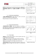
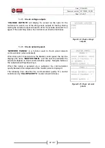
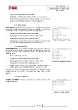
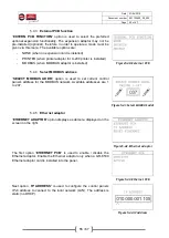
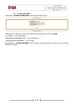
5.4.9
Reset defaults
“
RESET DEFAULTS
” clears memory and restores all configurations
back to factory default values.
The only exceptions are certain hardware configurations:
Loops (enabled/disabled), External PCB function, Ethernet PCB
(enabled/disabled).
Figure5-49.Reset defaults
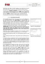
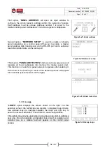
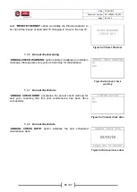
5.5
Clear events log
The
“
CLEAR EVENTS LOG
” option deletes all event log entries in the
control panel. This option should be executed after every initial
installation so event logs during commissioning are cleared and real
time operation events are logged.
Figure5-50.Clear events log
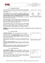
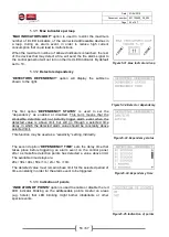
5.6
Initializing alarm counter
The
“
INIT. ALARM COUNTER
” option is used to reset the alarm
counter back to “0”. The number of recorded alarms can be seen in
“MENU > INFORMATION > ALARMS COUNTER”.
This option is only accessible with level 4 access, meaning that the
technician must have physical access to the dip-switch selector on the
back side of the CPU board and switch selector 1 to ON position.
After executing this function, dip-switch selector 1 shall be set back to
OFF position.
Figure5-51.Init. alarm counter
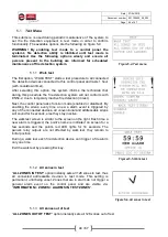
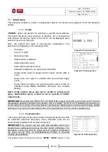
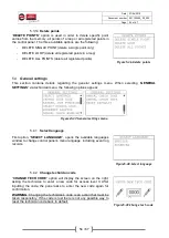
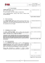
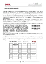
5.7
PC Communication
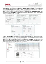
The “
PC COMMUNICATION
” option is used to download/upload
configurations from or to a PC via USB cable, running the
BSR-100X
software application
. When selected, a confirmation message as the
screen on the right will be displayed. When the PC communication
starts, the control panel will be awaiting for a request from the PC.
During data transmission or reception, a relative message
(TRANSMITTING DATA or RECEIVING DATA) will appear on screen.
Figures5-52.PC Communication


