


17
16
GB
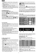
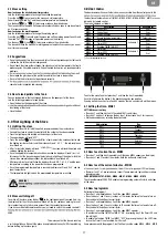
4.0 User menu
The board comes with a user/technician menu, accessible from the control panel. In this
the functions of automatic on / off (MN05 - MN06 - MN07 - MN08 - MN09 - MN10) are avai-
lable only by remote control.
The menu is divided as follows:
Menu
Description
Available for
MN01
Current day
User
MN02
Current hour
User
MN03
Current minutes
User
MN04
Access technical parameters
Technician (*)
MN05
Timer ON 1
Schedule 1
User
MN06
Timer OFF 1
User
MN07
Enabling TIMER1 ON/OFF
User
MN08
Timer ON 2
Schedule 2
User
MN09
Timer OFF 2
User
MN10
Enabling TIMER2 ON/OFF
(*) See corresponding section
To enter the menu You must press key 1 and then the key 3 repeatedly.
Each time You press the button 3, the board changes by one position.
If you do not touch any key for at least 60 seconds, there is an automatic exit from menu.
4.1 Setting the time - MN01
SETTING the current day
•
Press key 1 and then key 3 until the code MN01 is on display.
•
Press key 1 and key 2 to change the day (key 1 for decrease, key 2 for increase).
•
Set the desired days by referring the below table:
Abbreviation
Day
DAY1
Monday
DAY2
Tuesday
DAY3
Wednesday
DAY4
Thursday
DAY5
Friday
DAY6
Saturday
DAY7
Sunday
OFF
4.2 How to set current hour - MN02
•
Press key 1 and then key 3 repeatedly until the code MN03 appears on the display.
•
Press keys 1 and 2 to select the minutes. Hold the buttons to scroll faster.
4.3 How to set the current minutes - MN03
•
Premere i tasti 1 e 2 per selezionare i minuti. Tenere premuto i pulsanti per scorrere
più velocemente.
CHRONOTHERMOSTAT –MN05 - MN06 - MN07 - MN08 - MN09 - MN10
The chronothermostat FUNCTION enables to programming automatic starts and stops
of the stove.
4.4 How to programm
Referring to the program 1
•
Press key 1 and repeatedly key 3 until the code MN05 appears.
•
Press the keys 1 and 2 to vary in steps of 10 minutes the time of automatic turn on.
Press and hold the buttons to scroll faster.
•
Press key 1 and repeatedly key 3 until the code MN06 appears.
•
Press the keys 1 and 2 to vary in steps of 10 minutes the time of automatic turn off.
Press and hold the buttons to scroll faster.
•
Press key 1 and repeatedly key 3 until the code MN07 appears.
•
To enable the function TIMER1 set MN07 "ON" by pressing key 2 the Timer LED and
this will light.
•
To enable the function TIMER1 set MN07 "OFF" by pressing the key 2 the LED Timer,
in case the Timer 2 is not enabled, it will turn off.
Same procedure with the program 2, but You’ll only use the codes MN08 - MN09 - MN10.
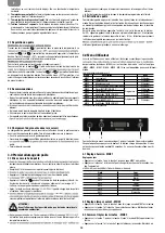
2
3
1
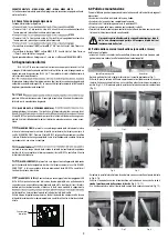
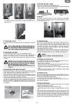
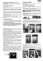
2.1 Stove setting
How to change the wished room temperature
Join the following procedure to change the wished temperature:
Press the key (1) once to enter the menu and set temperature.
You will read the word “Set” and the wished temperature on the display.
Use the keys (2) e (3) to increase or reduce the wished value.
The stove will leave the menu Set temperature automatically as soon as you do not work
on it for some seconds.
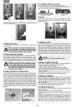
How to change the working power
Join the following procedure to change the working power:
Press the key (1) once to enter the menu and set the working power. You will read
the word “Pot” and the range of 5 possible powers on the display.
Use the keys (2) and (3) to increase or reduce the wished value.
The stove will leave the menu Set working power automatically as soon as you do not
use it for some seconds.
2.2 Suggestions
•
Do not continuously turn the stove on and off as this could provoke sparks that could
shorten the life of the electrical components.
•
Do not touch the stove with wet hands: the stove has electrical components that could
produce sparks if handled incorrectly. Only authorized technicians can resolve possible
problems.
• Never open the glass door of the pellet stove while the stove is in oper
ation.
• Be sure th
at the brazier basket is positioned correctly.
some holes for inspection and cleaning.
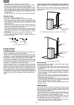
2.3 How to load pellets in the tank
You can load pellets in the tank through the door on the upper part of the stove.
Join the following procedure to load pellets:
• Open the door on the upper part of the stove;
functioning of the stove);
• Close the doo
r.
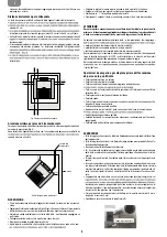
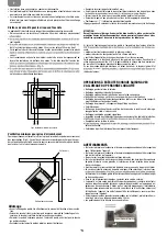
3.0 First Lighting of the Stove
3.1 Lighting the stove
•
F
ill the container 3/4 full with the pellets recommended by the manufacturer;
• Connect the stove to an electrical outlet with the cable th
a
t has been supplied;
• Press the lighting
switch loca
ted on the back part of the stove;
•
The upper display will read
“OFF”;
•
Press the button for 2 seconds. After a few moments the smoke extractor and
the lighting resistor will start and the display will read “
”;
the led resistence
is switched on.
•
After 1 minute the display will read
”, the stove will load the pellets and
continue lighting the resistor;
•
Once the appropriate temperature has been reached the display will read “
”:
this means that the stove has begun the last phase in lighting, at the end of which the
stove will be completely opera
tional; the led resistence is
switched off.
•
After several minutes of ventilation the display will read “ON 1-2-3-4-5” and the room
temperature, according to the power tha
t has been programmed;
•
Once the programmed temperature is reached the display will read “ECO” and the
room tempera
ture;
•
The temperature led lights when the programmed tempera
ture is reached;
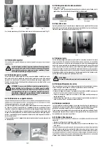
3.2 Stove switching off
To switch off the stove, press the key on the control board until you read
on
the display. After the stove has been switched off, the fan continues working for a set
time in order to grant a fast smokes exhaust from the combustion chamber.
If you have a model with remote control, you just need to switch the remote control off
SEND.
This warns you that the stove is running
a switching off phase. Wait until the phase is completed and the key On/Off stops blinking
before starting up the stove again.
WARNING!
chamber.
Men manuale Extrastove 3 tasti_Layout 1 17/10/12 09.30 Pagina 16
FIRE STAB.
LOAD PELL.
“
ACC.
"COOL"
-
+
AL
1
2
3


