40496501TH Draft Version
71
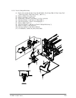
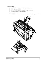
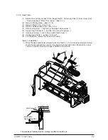
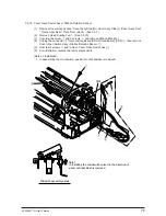
3.3.18 Printing Head
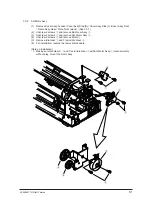
(1)
Lean Frame Assy Rear backward and open Access Cover.
(2)
Move the printing head to the recess on the right seen from the front.
(3)
Pull out Ribbon Guide
1
upward.
(4)
Unscrew 2 screws
2
and remove Printing Head
3
from the connector.
(5)
For installation, reverse the removal procedure.
(Note on Installation)
1. The head should be installed according to Section 9, Procedure for Installing Print Head in
4 ADJUSTMENTS.
1
2
3
Summary of Contents for PACEMARK 4410
Page 1: ...PACEMARK 4410 PRINTER SERVICE HANDBOOK...
Page 52: ...40496501TH Draft Version 52 Figure 3 1 3 2 Parts Layout...
Page 95: ...40496501TH Draft Version 95...
Page 168: ...XXXXXXXXTH Draft Version 8 5 Fig 8 5 45 38 38 40 42 39 44 44 122 41...
Page 169: ...XXXXXXXXTH Draft Version 8 6 142 141 11 119 Fig 8 6...
Page 170: ...XXXXXXXXTH Draft Version 8 7 Fig 8 7 105 102 61 33 104 100 101...

