40496501TH Draft Version
68
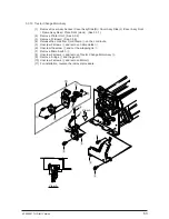
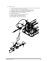
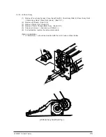
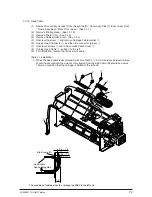
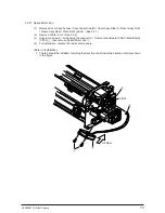
3.3.15 Space Motor
(1)
Remove Cover Assy Access / Cover Assy Side (R) / Cover Assy Side (L) /Cover Assy Front
/ Frame Assy Rear / Plate Front (stuck). (See 3.3.1)
(2)
Remove Printer Unit. (See 3.3.2)
(3)
Remove the stopper
1
.
(4)
Screw down 2 fixing screws
2
on Idle Pulley Bracket. Move the pulley into the arrow direction
to loose the belt, then fasten the screws.
(5)
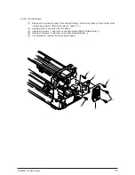
Remove PG Cooling Fan. (See 3.3.5)
(6)
Unscrew 2 screws
4
and remove PG Fan Bracket
5
.
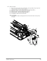
(7)
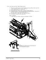
Unplug connectors
7
to Interlock Switch Cord Assy
B
.
(8)
Unplug connectors
8
,
9
to Interlock Switch
0
, and release the cords from the cordclamps
on the cord route.
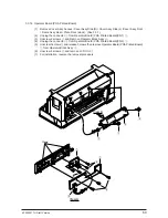
(9)
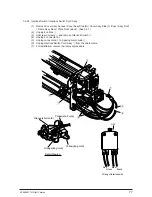
Unscrew 1 screws
C
and remove FG Mesh
3
.
(10) Unscrew 4 screws
A
and remove Space Motor
6
.
(11) For installation, reverse the removal procedure.
(Note on Installation)
1. After assembling the motor, adjust the position of the idle pulley bracket with screw
2
so that
the space belt should be positioned at the center between the idle pulley and motor pulley,
and the vertical fluctuation of belt be 0.5mm or less when the carriage is shifted to right and
left. When the carriage is shifted to right and left, press the interlock switch
0
off so that the
load of shifting it can be reduced.
8
A
A
9
0
1
2
2
B
7
6
3
C
4
5
OFF
Idle Pulley Bracket
0.5mm or less
0.5mm or less
Junction Board
Brack
Blew
Green
Red
Wiring of interlok swith
Summary of Contents for PACEMARK 4410
Page 1: ...PACEMARK 4410 PRINTER SERVICE HANDBOOK...
Page 52: ...40496501TH Draft Version 52 Figure 3 1 3 2 Parts Layout...
Page 95: ...40496501TH Draft Version 95...
Page 168: ...XXXXXXXXTH Draft Version 8 5 Fig 8 5 45 38 38 40 42 39 44 44 122 41...
Page 169: ...XXXXXXXXTH Draft Version 8 6 142 141 11 119 Fig 8 6...
Page 170: ...XXXXXXXXTH Draft Version 8 7 Fig 8 7 105 102 61 33 104 100 101...

