background image

OKI Data Infotech Corporation CONFIDENTIAL 

Chapter 6 Parts Replacement (Disassembly/Reassembly) 


6-60 

6.8.2 

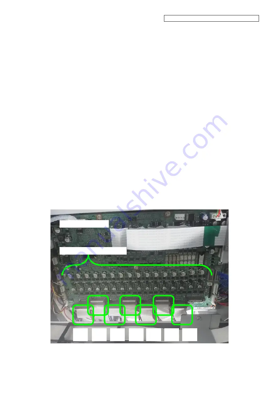
CABLE(HEAD)2-ASSY(MW) 

<Removal> 

1. 

Press the 

CANCEL

 button and the 

POWER

 button on the operation panel at 

the same time to turn the printer off. Turn 
off the main power switch at the back of 
the printer. 

2. 

Lower the CAPPING-UNIT-MW to move 
the carriage to the left. 

3. 

Remove: 
    - COVER(L)ASSY-MW 
    - COVER

Y-RAIL)-SL-MW. 

For the procedure, see 

6.3

. 

4. 

Remove the COVER-CARRIAGE-MW 
(see 

6.7.1

)

5. 

Remove the


CABLE(HEAD)2-ASSY(MW) from the 
PCB-ASSY-HCB1M. 


PCB-ASSY-HCB1M 

CABLE(HEAD)2-ASSY(MW) 

Print 

head 1 


Print 

head 2 


Print 

head 3 


Print 

head 4 


Print 

head 5 


Print 

head 6 


Print 

head 7 


Summary of Contents for IP-6620

Page 1: ...OKI Data Infotech Corporation CONFIDENTIAL IP 6620 Solvent Ink Color Inkjet Printer U00130319805 Maintenance Manual...

Page 2: ...h edition U00130319805 December 2015 Sixth edition Copyright 2015 OKI Data Infotech Corporation All rights reserved OKI Data Infotech Corporation reserves the right to make changes without notice to t...

Page 3: ...maintenance items when they differ depending on models Caution make sure to read the following Always disconnect the power cord from the power outlet when opening the controller box or the power suppl...

Page 4: ...IS model 1 10 1 4 1 Front view 1 10 1 4 2 Rear view 1 11 1 4 3 Inner parts view 1 12 1 4 4 Printer heater section 1 13 1 4 5 Operation panel 1 14 1 4 6 Options 1 15 1 5 Maintenance Space 1 16 Chapter...

Page 5: ...3 19 3 4 2 ADJUST 3 47 3 4 3 MAINTENANCE 3 67 3 5 Special Operations 3 97 3 5 1 Language setting mode 3 98 3 5 2 Post head replacement guidance skip mode 3 98 3 5 3 POC Skip Mode Not available to user...

Page 6: ...ctional print position has not been adjusted 5 56 5 4 6 The media advance has not been adjusted 5 57 5 4 7 The start maintenance has not been performed 5 57 5 4 8 It is recommended to perform PH recov...

Page 7: ...write Error 5 90 5 5 15 System Error 1650 EEPROM Initialization Check Error 5 91 5 5 16 System Error 1660 RSM Mask Memory Read write Error 5 91 5 5 17 System Error 1670 ATG Register Read write Error...

Page 8: ...IRE END Detection Error 5 135 5 5 49 System Error 2c0X Ionizer Voltage Error 5 137 5 5 50 System Error 2d0X Automatic Print Adjustment Calibration Error 5 138 5 5 51 System Error 3020 RSM PTG FIFO Con...

Page 9: ...COVER SIDE L MW 6 8 6 3 7 COVER SIDE R MW 6 9 6 3 8 FAN REAR ASSY MW 6 10 6 3 9 OP PANEL UNIT MW 6 11 6 3 10 COVER PINCH D 64 MW 6 12 6 3 11 COVER SUBTANK MW 6 12 6 3 12 SWITCH Interlock ASSY and SWIT...

Page 10: ...8 4 PCB ASSY HCB1M 6 63 6 8 5 CASE HEAD MW ASSY 6 66 6 8 6 LINEAR ENCODER ASSY MW 6 67 6 8 7 FAN EL UNIT ASSY MW 6 69 6 8 8 PCB ASSY ADJ1 6 70 6 8 9 FFC ADJ 6 72 6 8 10 Ionizer 6 77 6 8 11 CAM UD 6 8...

Page 11: ...6 14 Disassembling and Reassembling the Heater Section 6 120 6 14 1 PAPER GUIDE DELIVERY64 MW ASSY with heater 6 120 6 14 2 PAPER GUIDE FEEDING64 MW ASSY with heater 6 122 6 14 3 PLATEN64 MW ASSY 6 12...

Page 12: ...PLATE CARRIAGE CAP MW Adjustment 7 30 7 9 REMAINING INK SENSOR MW LCIS Adjustment 7 31 7 10 Linear encoder position adjustment 7 39 Chapter 8 Operation Mechanism 8 1 Overview of System Operation Mecha...

Page 13: ...2 Block diagram 8 41 Appendix IP 6620 Wiring Diagram Appendix 1 Power Interlock Wiring Diagram Appendix 2 Appendix 2 Carriage IPB5 Interface Wiring Diagram Appendix 3 Appendix 3 Carriage ADJ1 Interfac...

Page 14: ...and part names printer interior 1 12 Figure 1 10 Heater names and locations sectional view 1 13 Figure 1 11 Operation panel 1 14 Figure 1 12 Maintenance space 1 16 Figure 6 1 Name of each part of the...

Page 15: ...ng problems and complaints Check the details of the problem and the circumstances when the problem occurred Check details of the problem and the circumstances that existed when the problem occurred Ch...

Page 16: ...g E rings commercially available Flat head screwdriver short 1 Flat head precision screwdriver 1 For removing E rings commercially available Hexagon button wrench 1 Size 5 6 Wrench 1 Size 13 Pliers or...

Page 17: ...or draining one ink color CAPPING SEAL TOOL HV 1 For checking leak tightness of the capping unit Table 1 3 Consumables Name Quantity Remarks Grease for synchro belt and decelerating belt 1 Grease EM...

Page 18: ...inter and the part names 1 3 1 Front view 1 Front cover 2 Maintenance cover 3 Capping cover 4 Operation panel 5 Output paper guide 6 Take up reel unit 7 Pressure roller lever Moves together with the p...

Page 19: ...inter power switch 14 USB connector 15 Media holder 16 Media jack 17 Media support 18 Caster 19 Pressure roller lever Moves together with the pressure roller lever at the printer front side 20 Install...

Page 20: ...NTIAL Chapter 1 Overview of Maintenance Workflow 1 6 1 3 3 Inner parts view 21 Carriage 22 Wiping unit 23 Capping unit 24 Media edge guards 25 Platen 26 Ink tray Figure 1 4 External view and part name...

Page 21: ...The printer is equipped with three heaters to fix ink on the print media and stabilize the print quality 27 Preheater 28 Printheater 29 Afterheater These three heaters are controlled individually Fig...

Page 22: ...ation panel The buttons LEDs and LCD are placed on the operation panel of the printer as shown below The buzzer is used to notify the operator when an error occurs or an invalid button is pressed The...

Page 23: ...Maintenance Workflow 1 9 1 3 6 Options Exhaust attachment option A unit used to install the exhaust air duct to the printer 2 inch flange option A flange used to install media rolls with 2 inch cores...

Page 24: ...the part names 1 4 1 Front view 1 Front cover 2 Maintenance cover 3 Capping cover 4 Operation panel 5 Output paper guide 6 Take up reel unit 7 Pressure roller lever Moves together with the pressure r...

Page 25: ...inter power switch 15 USB connector 16 Media holder 17 Media jack 18 Media support 19 Caster 20 Pressure roller lever Moves together with the pressure roller lever at the printer front side 21 Install...

Page 26: ...TIAL Chapter 1 Overview of Maintenance Workflow 1 12 1 4 3 Inner parts view 22 Carriage 23 Wiping unit 24 Capping unit 25 Media edge guards 26 Platen 27 Ink bottle Figure 1 9 External view and part na...

Page 27: ...The printer is equipped with three heaters to fix ink on the print media and stabilize the print quality 28 Preheater 29 Printheater 30 Afterheater These three heaters are controlled individually Fig...

Page 28: ...ation panel The buttons LEDs and LCD are placed on the operation panel of the printer as shown below The buzzer is used to notify the operator when an error occurs or an invalid button is pressed The...

Page 29: ...Maintenance Workflow 1 15 1 4 6 Options Exhaust attachment option A unit used to install the exhaust air duct to the printer 2 inch flange option A flange used to install media rolls with 2 inch cores...

Page 30: ...r 1 Overview of Maintenance Workflow 1 16 1 5 Maintenance Space Figure 1 12 shows space required for the printer maintenance Figure 1 12 Maintenance space CIS 6100 LCIS 6400 1000 2000 1500 1500 3940 2...

Page 31: ...form the maintenance operations 2 1 1 How to check the daily maintenance execution rate Daily maintenance execution rate can be checked on the printer operation panel and CP_Manager Procedure to check...

Page 32: ...ta Infotech Corporation CONFIDENTIAL Chapter 2 Inspection and Maintenance 2 2 Procedure to check the daily maintenance execution rate on CP_Manager In Basic mode In Advanced mode Select the Maintenanc...

Page 33: ...it cleaning and normal cleaning Waste ink bottle check and replacement Wiper cleaning liquid check and supply Wiper blade cleanliness check and replacement Maintenance when a message is displayed Wast...

Page 34: ...o the User s Guide to replace the following parts Wiper blades rubber and sponge Wiper sponge Wiper cleaning liquid 2 4 Cleaning If the printer exterior is dirty clean it with a soft cloth moistened w...

Page 35: ...very dirty wipe them with a soft cloth moistened with water or a water diluted neutral detergent Only the metal parts without paint can be cleaned with a soft cloth moistened with cleaning liquid Note...

Page 36: ...e front cover and put a soft cloth onto ink stains on the platen to soak them up Be careful not to spread the ink on the platen 2 Wipe off the ink marks on the platen with a soft cloth moistened with...

Page 37: ...wn button and the press the OK button 5 Press the OK button 6 After the carriage has stopped moving open the COVER CENTER F and COVER L ASSY MW in that order Clean the print heads when the three condi...

Page 38: ...n the picture to the right the part with the glossy surface If the surface is damaged it may cause print defects 8 When the ink has dissolved and is not forming continuous lines as shown in the pictur...

Page 39: ...km or less Change the color specifications following the procedure below 1 Replace the PUMP F ASSY MW for the seventh color Gy with a new one see 6 10 4 for the procedure 2 Replace the CAP ASSY MW for...

Page 40: ...F ASSY MW U00130624700 180h Same as on the left Can be replaced only when malfunctioning 1 5 Y DRIVE MOTOR ASSY U00130619200 17 km Same as on the left Can be replaced only when malfunctioning 1 6 DRIV...

Page 41: ...panel are classified as follows User mode Functions used by standard users Maintenance mode Functions used for initial adjustments at the factory and field maintenance This chapter describes only ope...

Page 42: ...ton is pressed the buzzer indicating an invalid key sounds However the password entry screen is displayed 2 Enter the password The password depends on the operation mode as follows Operation mode Pass...

Page 43: ...n Ver X XX on the bottom left corner of the CP_Manager screen while holding the Ctrl key to display the password entry screen Then enter the password You can perform this operation with Display or Pan...

Page 44: ...cyan can only be displayed and operated from the operation panel not from CP_Manager Panel button Description MENU button Used to display various information items and the system settings The displaye...

Page 45: ...the printer emits a warning Warning 3 when the printer emits a warning Warning 4 when the printer emits a warning Followed by other warnings if any Ink information Number of bottles that can be suppl...

Page 46: ...C Y K M Gy 7 color CIS model only Ink manufacturing date CIS model only Lc some menus are omitted below Ink waste percent Total used ink Lc some menus are omitted below Remaining media Print length T...

Page 47: ...sensors Edge Home position Cap position Wiper position Supply side media Output side media Roll end Lever Front cover R Front cover L Waste ink bottle Auto adjust R Auto adjust G Auto adjust B Ionize...

Page 48: ...y Remaining ink 3 LCIS model only Remaining ink 4 LCIS model only Remaining ink 5 LCIS model only Remaining ink 6 LCIS model only TUR sensors TUR drawer R TUR drawer L Slack upper limit Slack lower li...

Page 49: ...Select preset number Edit preset name Media advance priority Media advance adjustment value Bidirectional adjustment value 1 Lc_L Lc_R Lm_L Lm_R C_L C_R Y_L Y_R K_L K_R M_L M_R Gy_L with 7 color prin...

Page 50: ...emaining media monitoring system firmware ver 3 00 and later only Set remaining media Print remaining media system firmware ver 3 00 and later only Unwind media Setting System Subscription code Langua...

Page 51: ...ead heaters Fans Rear fans Carriage fans Exhaust fan Suction fan 1 Suction fan 2 Suction fan 3 Suction fan 4 Motors Pump Wipe motor Cap motor TUR unit motor Ink supply motor 1 Ink supply motor 2 Ink s...

Page 52: ...aft LCIS model only Fast production Production Standard Quality High quality Max quality Media advance manual Draft LCIS model only 1 pattern 3 patterns Feed media Back feed media Fast production 1 pa...

Page 53: ...value Lm_R Bidirectional adjustment value C_L Bidirectional adjustment value C_R Bidirectional adjustment value Y_L Bidirectional adjustment value Y_R Bidirectional adjustment value K_L Bidirectional...

Page 54: ...0 Enter Lm 01 02 some menus are omitted below some menus are omitted below Mechanical adjustment Print head position adjustment Print pattern Feed media Back feed media Enter print head adjustment val...

Page 55: ...t value Cap position adjustment value Wiping position adjustment value Remaining ink sensor adjustment LCIS model only Print head voltage offset Offset value Lc_L Offset value Lc_R Offset value Lm_L O...

Page 56: ...print heads and ink system Prime ink system Drain ink LCIS model only Fill cap with ink Adjust print head height Set print head for check Nozzle check Replace print head Print head check pattern Prime...

Page 57: ...tern Print mode Smart pass Direction Print length Number of copies Color Horizontal stripes Checkerboard Grid 1 dot line Solid color Gradation Media advance accuracy Line width check Feed media Back f...

Page 58: ...ZZLE PRINT button Used to perform nozzle print before system firmware ver 3 00 Used to perform nozzle print and automatic nozzle map system firmware ver 3 00 and later NOZZLE PRINT AUTO NOZZ MAP befor...

Page 59: ...ote Temperature unit appearing in this section can be converted as follows Fahrenheit Celsius x 9 5 32 degrees 3 4 1 MENU 3 4 1 1 INFORMATION 1 TOTAL PRINT LENGTH Press the MENU button select INFORMAT...

Page 60: ...on Select VERSION INFO with the Up and Down buttons and then press the OK button a ATG version Displays the version of the ATG FPGA b RSM version Displays the version of the RSM FPGA c PTG version Dis...

Page 61: ...order corresponds to the color order After the last color the first color is displayed again Use the Up and Down buttons to select the information you want to display for the selected print head and...

Page 62: ...the information cannot be determined because of the case below No print head is installed on the printer or A print head information error is detected V is displayed d VOLTAGE RANK B CC Print head co...

Page 63: ...is displayed in unit of 1 million aligned to the left with zero suppression If the information cannot be determined because of the case below No print head is installed on the printer or A print head...

Page 64: ...below No print head is installed on the printer or A print head information error is detected is displayed Example When Y and Lc ink have been used Y Lc is displayed i PRINT HEAD TYPE CC Print head c...

Page 65: ...ensors change The CHECK SENSORS operation is not available when an error has occurred Press the MENU button select INFORMATION with the Up and Down buttons and then press the OK button Select SENSOR I...

Page 66: ...ION 1 Wiper is in the home position SUPPLY SIDE MEDIA 1 Media is installed OUTPUT SIDE MEDIA ROLL END 1 End of the roll media LEVER 1 Lever is activated FRONT COVER R 1 Cover is closed FRONT COVER L W...

Page 67: ...XX XV PRINTER SENSORS IONIZER XX XV PRINTER SENSORS AUTO ADJUST B XX XV PRINTER SENSORS AUTO ADJUST G XX XV PRINTER SENSORS AUTO ADJUST R XX XV PRINTER SENSORS WASTE BOTTLE PRINTER SENSORS FRONT COVER...

Page 68: ...INK SUPPLY PUMP 3 INK SUPPLY PUMP 4 INK SUPPLY PUMP 5 INK SUPPLY PUMP 6 INK SUPPLY PUMP 7 INK TRAY 1 CIS only 1 Ink tray installed INK TRAY 2 CIS only INK TRAY 3 CIS only INK TRAY 4 CIS only INK TRAY...

Page 69: ...Y 2 to 7 Same for SUBTANK FULL 2 to 7 Same for SUBTANK END 2 to 7 Same for REMAIN INK 2 to 7 INK SYSTEM SENSORS REMAIN INK 1 X INK SYSTEM SENSORS RESERV DRAWER X INK SYSTEM SENSORS SUBTANK END 1 X INK...

Page 70: ...due to the number of displayed characters Sensor Sensor value TUR DRAWER R 1 TUR unit is installed TUR DRAWER L 1 TUR unit is installed SLACK UPPER LIMIT 1 Upper limit light passes through SLACK LOWE...

Page 71: ...with the Up and Down buttons Thermistor Thermistor value AMBIENT T Ambient temperature PREHEATER Media preheater temperature PRINTHEAT Media printheater temperature AFTERHEAT Media afterheater temper...

Page 72: ...temperature unit set in the system settings Note Minus sign is displayed when necessary however plus sign is not displayed Same for HEAD 2 to 7 Same for HEAD IC 1B to 7B THERMISTORS HEAD IC 1A XXX X...

Page 73: ...press the OK button Select PART REPLACEMENT with the Up and Down buttons and then press the OK button a PART REPLACEMENT This menu is used to configure whether or not to display warnings regarding co...

Page 74: ...nfigure the system time HH Hours MM Minutes Setting range 00 00 to 23 59 d SERIAL No This menu is used to configure the board serial number XXXXXXXX Eight character serial alphanumeric characters e IN...

Page 75: ...backup area i LOAD PRINTER SET This menu is used to load the parameters from the backup area j NUMBER OF COLORS CIS model only This menu is used to configure the number of colors YYY Setting after ch...

Page 76: ...re whether the ink system has been primed or not YYY Setting after change PRIMED The subtanks and the ink circuits are filled with ink NOT PRIMED DRY The subtanks and the ink circuits have never been...

Page 77: ...ress the OK button Select MEDIA HEATER SET with the Up and Down buttons and then press the OK button Set the standby temperature for the preheater and the printheater Fahrenheit Celsius YY Standby tem...

Page 78: ...own buttons and then press the OK button Select ACTUATORS with the Up and Down buttons and then press the OK button a HEATERS This menu is used to operate the actuators related to the heaters Select H...

Page 79: ...eater 55 C Preheater 55 C 45 40 45 Each heater operates until it reaches the following temperature required to adjust the platen flatness Afterheater 45 C Printheater 40 C Preheater 45 C ii PRINT HEAD...

Page 80: ...o operate the actuators related to the fans Select FANS with the Up and Down buttons and then press the OK button Select a fan with the Up and Down buttons and then press the OK button FANS SUCTION FA...

Page 81: ...he carriage cooling fan YYY Setting after change Parameter Description Remark OFF Stopped ON Activated Power 100 iii EXHAUST FAN This menu is used to operate the exhaust fan YYY Setting after change P...

Page 82: ...scription Remark WIPE MOTOR STOP Stopped WIPE MOTOR FAST Wipe motor runs at high speed Runs until WIPE MOTOR STOP is selected However stops automatically when it has been running for a long time WIPE...

Page 83: ...rk OFF Stop the TUR unit motor ON Activate the TUR unit motor Power 100 iv INK SUPPLY MOTOR 1 to 7 This menu is used to operate the motors of the ink supply pumps 1 to 7 YYYYYYYY Setting after change...

Page 84: ...th the Up and Down buttons and then press the OK button i AIR RELEASE SOL 1 to 3 This menu is used to operate the air release solenoid YYYYYY Setting after change Parameter Description Remark CLOSE St...

Page 85: ...es OFF The system prevents the clutch from running continuously in case the user forgets to deactivate it e LEDS This menu is used to operate the LEDs RGB for automatic print adjustment Select LEDS wi...

Page 86: ...YYY Setting after change Parameter Description Remark OFF Stop the ionizer ON Activate the ionizer g PRINTER POWER This menu is used for power systems diagnosis Select a parameter with the Up and Dow...

Page 87: ...ion and production print modes 2 STD QUALITY Print a check pattern for standard and quality print modes 3 HIGH QUALITY Print a check pattern for high quality print mode 4 MAX QUALITY Print a check pat...

Page 88: ...the OK button Select FEED MEDIA or BACK FEED MEDIA with the Up and Down buttons Hold the OK button pressed to feed or backfeed the media Release the OK button to stop feeding or backfeeding and to re...

Page 89: ...th the Up and Down buttons and then press the OK button Select PH POSITION ADJUST with the Up and Down buttons and then press the OK button Select PRINT PATTERN with the Up and Down buttons and then p...

Page 90: ...u select FEED MEDIA or BACK FEED MEDIA with the Up and Down buttons Hold the OK button pressed to feed or backfeed the media Release the OK button to stop feeding or backfeeding and to return to the p...

Page 91: ...aligned with the K print head line For example the line for Lc is not aligned for 2 but is aligned for 2 so the adjustment value to enter is 2 For each color as the adjustment value enter the value o...

Page 92: ...C XX for each color with the Up and Down buttons and then press the OK button CC Print head color X Current value Y Value after change Setting range 32 to 31 Enter the value of the pattern with the li...

Page 93: ...PATTERN Select NOZZLE POS ADJ with the Up and Down buttons and then press the OK button Select PRINT PATTERN with the Up and Down buttons and then press the OK button Press the OK button to display t...

Page 94: ...rn to the previous screen c Nozzle position adjutsment value In the NOZZLE POS ADJ menu select X Y with the Up and Down buttons and press the OK button CC Print head color X Current value Y Value afte...

Page 95: ...button Press the CANCEL button to return to the previous screen without modifying the value 3 PH SLANT CHECK This menu is used to print the print head slant check pattern a PRINT PATTERN Select PH SLA...

Page 96: ...select FEED MEDIA or BACK FEED MEDIA with the Up and Down buttons Hold the OK button pressed to feed or backfeed the media Release the OK button to stop feeding or backfeeding and to return to the pr...

Page 97: ...ons and then press the OK button Select PRINT PATTERN with the Up and Down buttons and then press the OK button Press the OK button to display the print confirmation screen then press the OK button ag...

Page 98: ...EDIA or BACK FEED MEDIA with the Up and Down buttons Hold the OK button pressed to feed or backfeed the media Release the OK button to stop feeding or backfeeding and to return to the previous screen...

Page 99: ...NT PATTERN Select EDGE SENSOR ADJUST with the Up and Down buttons and then press the OK button Select PRINT PATTERN with the Up and Down buttons and then press the OK button Press the OK button to dis...

Page 100: ...the edge sensor side position In the EDGE SENSOR ADJUST menu select SENSOR ADJ VAL with the Up and Down buttons and then press the OK button Select XX X YY Ymm with the Up and Down buttons and then pr...

Page 101: ...nu is used to adjust the cap position Select CAP POS ADJ VALUE with the Up and Down buttons and then press the OK button Select X X Y Ymm with the Up and Down buttons and then press the OK button XX X...

Page 102: ...ss the OK button CC Ink color X XX Adjustment value A Y YY Adjustment value B Select an ink color with the Up and Down buttons and then press the OK button CC Ink color X XX Adjustment value A Y YY Ad...

Page 103: ...appear Post replacement adjustment Select RMNG INK SNSOR ADJ with the Up and Down buttons and then press the OK button Select POST REPLAC ADJ with the Up and Down buttons and then press the OK button...

Page 104: ...tment value A Y YY Adjustment value B Note After the adjustment is complete write the adjustment values A and B on the label for remaining sensor replacement small and paste it to the position of the...

Page 105: ...age is displayed When the drawer is open When an error has been detected in the adjustment result An error occurs if the remaining ink sensor has not been replaced correctly After the error has occurr...

Page 106: ...ton CC Print head color P Print head right or left X X Current offset value CC Print head color P Print head right or left X X Current value Y Y Value after change Select a digit to modify with the Ri...

Page 107: ...tons and then press the OK button 1 NOZZLE CHECK This menu is used to print a NOZZLE CHECK pattern Select NOZZLE CHECK with the Up and Down buttons and then press the OK button Press the OK button The...

Page 108: ...ing Press the power switch to turn the printer off Confirm that the print has shut down completely and then replace the print head After you have replaced the print head press power switch to turn the...

Page 109: ...ns and then press the OK button Move the cursor with the Right and Left buttons and toggle a digit with the Up and Down buttons A digit that has been toggled disappears Finish the selection and press...

Page 110: ...ns and toggle a digit with the Up and Down buttons A digit that has been toggled disappears Finish the selection and press the OK button Note Do not select numbers of tubes that have not been replaced...

Page 111: ...ridges are not installed install them Press the OK button to start priming the system The pump stops running Remove the jig SINGLE COLOR FILLING TOOL MV and press the OK button Check that a waste ink...

Page 112: ...Up and Down buttons and then press the OK button Move the cursor with the Right and Left buttons and toggle a digit with the Up and Down buttons A digit that has been toggled disappears Finish the sel...

Page 113: ...Press the OK button The pump stops running Note Again check that the print heads and the jig SINGLE COLOR FILLING TOOL MV are correct Remove the jig SINGLE COLOR FILLING TOOL MV and press the OK butt...

Page 114: ...the OK button Move the cursor with the Right and Left buttons and toggle a digit with the Up and Down buttons A digit that has been toggled disappears Finish the selection and press the OK button Inst...

Page 115: ...two filter module joints remove the tube and then close the reservoir drawer X Ink color Check that a waste ink bottle is installed and press the OK button A normal cleaning is performed The draining...

Page 116: ...To remove air in a filter after replacing it Note Before starting the procedure put the printer in the idle state state with no errors and open and close the reservoir drawer to supply ink in the subt...

Page 117: ...tton 1 OPEN CAP Select OPEN CAP with the Up and Down buttons and then press the OK button Press the OK button to confirm the operation The caps open 2 CLOSE CAP This menu is used to operate the cappin...

Page 118: ...enu is used to move the carriage Select MOVE CARRIAGE with the Up and Down buttons and then press the OK button Select a parameter with the Up and Down buttons and press the OK button HOME POSITION Th...

Page 119: ...tions 3 79 5 REPLACE CAP This menu is used to condition the caps Select REPLACE CAP with the Up and Down buttons and then press the OK button Press the OK button to confirm the operation The operation...

Page 120: ...select COUNTERS with the Up and Down buttons and then press the OK button Select a parameter with the Up and Down buttons and press the OK button 1 ENTER VALUE This menu is used to enter values for th...

Page 121: ...or Select the ink color with the Up and Down buttons and press the OK button CC Ink color c Y MOTOR This menu is used to display and set the total print length for the Y motor XXXXX Length to display...

Page 122: ...perating time of the cap motor XXX Standard period for warning 3 digits YYYY Current amount of time 4 digits f CAPS This menu is used to display and set the cap operating time XXXX Standard period for...

Page 123: ...with the Up and Down buttons and press the OK button CC Ink color LCIS model This menu is used to display and set the operating time of the supply pumps CC Ink color Select the ink color with the Up...

Page 124: ...sed to reset the length of printed media Press the OK button to reset the counter or the CANCEL button to cancel RESET COUNTER SUBCART USAGE RESET COUNTER INK PUMP CYCLES TOTAL PRINT LENGTH RESET THIS...

Page 125: ...e total print length for the Y motor Press the OK button to reset the counter or the CANCEL button to cancel d Y MOTOR PULLEY This menu is used to reset the operating time of the Y motor pulley Press...

Page 126: ...ON PUMP This menu is used to reset the operating time of the suction pump h SUPPLY PUMP CIS model This menu is used to reset the number of cycles of the supply pumps CC Ink color Select the ink color...

Page 127: ...wn buttons and press the OK button CC Ink color i SUBCART USAGE This menu is used to reset the operating time of the supply pump CC Ink color Select the ink color with the Up and Down buttons and pres...

Page 128: ...measure the line width Parameter Description Remark PRINT Print the test pattern MODE Select the print mode SMART PASS Configure the smart pass setting Normally set it on DIRECTION Select between bid...

Page 129: ...e pattern to print and then follow the same procedure as for Vertical Stripes 1 VERTICAL STRIPES Select VERTICAL STRIPES with the Up and Down buttons and then press the OK button a PRINT Press the OK...

Page 130: ...DARD Standard Default STANDARD HD Standard high density CIS model only QUALITY Quality QUALITY HD Quality high density CIS model only HIGH QUALITY High quality HIGH QUAL HD High quality high density M...

Page 131: ...ark BIDIR Bidirectional direction Default SINGLE Unidirectional direction e LENGTH Default 400 mm f NO OF SHEETS Unit Number of sheet Range 1 to 99 Default 1 Unit mm Range 1 to 99999 NO OF SHEETS 01 0...

Page 132: ...nd BACK FEED MEDIA Select FEED MEDIA or BACK FEED MEDIA with the Up and Down buttons Hold the OK button pressed to feed or backfeed the media Release the OK button to stop feeding or backfeeding and t...

Page 133: ...pt the printing 2 PH SLANT CHECK Select PH SLANT CHECK with the Up and Down buttons and then press the OK button Press the OK button to confirm the execution You may press the CANCEL button to interru...

Page 134: ...ou may press the CANCEL button to interrupt the printing Move the cursor with the Right and Left buttons and toggle a digit with the Up and Down buttons A digit that has been toggled disappears Finish...

Page 135: ...ou may press the CANCEL button to interrupt the printing 6 CHECK BIDIRECTION1 to 4 Select CHECK BIDIRECTION1 with the Up and Down buttons and then press the OK button Press the OK button to confirm th...

Page 136: ...MEDIA or BACK FEED MEDIA with the Up and Down buttons Hold the OK button pressed to feed or backfeed the media Release the OK button to stop feeding or backfeeding and to return to the previous scree...

Page 137: ...s Special operation modes Power switch MENU button Language setting mode Enters directly the language menu in system in the user mode Power switch OK button Post head replacement guidance skip mode Af...

Page 138: ...r After a print head has been replaced normally the guidance after print head replacement is displayed when the printer starts This mode is used to skip this guidance After the printer has started in...

Page 139: ...ion mode or engineering mode entered the printer starts and enters the corresponding mode in the offline state This mode is used to Clear errors that have been saved for a long time Initialize the par...

Page 140: ...the printer with setting the language The following menu appears when The printer is turned on for the first time after shipping or when it is started with the Power MENU buttons held special mode If...

Page 141: ...again Set a unit of temperature and press the OK button Press the OK button to confirm the selected unit or press the CANCEL button to select a unit of temperature again End of language setting Note Y...

Page 142: ...ink system not primed the guidance to select the number of ink colors is displayed Select the number of colors with the Up and Down buttons and then press the OK button Press the OK button Press the O...

Page 143: ...n is displayed again Press the OK button without changing the setting Press the OK button Note If you change the number of color again the message prompting you to RESTART THE PRINTER will appear once...

Page 144: ...and Down buttons A digit that has been toggled disappears Finish the selection and press the OK button The OK button operation is disabled if incorrect print head combination is selected Note To prev...

Page 145: ...e tool and press the OK button Check that a waste ink bottle is installed and press the OK button The cleaning of the print head starts The priming of the print head starts The guidance ends when the...

Page 146: ...g operation or for backup The description below explains the information stored in each memory area RAM area Stores the current system data EEPROM area Stores the default values of system information...

Page 147: ...all EEPROM data in the factory default setting area of the flash memory Operation and start timing This storing can be performed with the maintenance mode s menu on the operation panel System menu SAV...

Page 148: ...erformed with the maintenance mode s menu on the operation panel System menu SAVE PRINTER SET Path 5 Restoring EEPROM backup data from the flash memory in EEPROM Flash EEPROM Processing Writes all the...

Page 149: ...he two kinds of tabs below with CP_Manager in maintenance mode Blue circled tab in the figure below While the tabs are also supported in user mode their functions have increased in maintenance mode Re...

Page 150: ...NTIAL Chapter 3 Maintenance Mode Functions and Operations 3 110 Function added in the Maintenance tab blue circled tab Functions added in the Mech Adjustment tab blue circled tab Functions added in th...

Page 151: ...fotech Corporation CONFIDENTIAL Chapter 3 Maintenance Mode Functions and Operations 3 111 Functions added in the Printer Info tab blue circled tab The Test Print tab that has been added in maintenance...

Page 152: ...fotech Corporation CONFIDENTIAL Chapter 3 Maintenance Mode Functions and Operations 3 112 The Sensor tab that has been added in maintenance mode only The Actuator tab that has been added in maintenanc...

Page 153: ...OKI Data Infotech Corporation CONFIDENTIAL Chapter 3 Maintenance Mode Functions and Operations 3 113...

Page 154: ...inspection and check item User Solution Service Engineer Inspection Assumed Replacement Part Reference to Check Replace Parts The paper guide does not become hot even after turning the heaters on Prin...

Page 155: ...rinter is in the print mode printing does not start with PREHEATING displayed on the operation panel Symptom User inspection and check item User Solution Service Engineer Inspection Assumed Replacemen...

Page 156: ...on fan power Reduce the power of the suction fan See Prevent the media from sticking and wrinkling in the User s guide Heater temperature setting Lower the heater temperature setting See Adjust the he...

Page 157: ...0 HEAD CABLE MW INKJET HEAD MW ROBOT CABLE MW CARRIAGE FFC MW PCB ASSY HCB1M ROBOT CABLE MW Printing is slow During print print heads are capped frequently Symptom User inspection and check item User...

Page 158: ...rts Clogged nozzles cannot be cleared Damaged media edges If the media is damaged with some sections coming out from the edge guards it may contact the heads nozzle surfaces and cause nozzles to clog...

Page 159: ...s the media type correctly The media winding mode is optimal for the installed media Check that the leading edge of the media output from the printer is installed straight to the TUR unit paper tube T...

Page 160: ...for poor print quality But for other cases of error the error LED lights up and the relevant error message appears on the LCD Poor print quality is checked mainly by printing a NOZZLE CHECK pattern W...

Page 161: ...INKJET HEAD MW The operating environment is outside the specification of the Printer Raise the ambient temperature to 15 C or more 20 to 25 C recommended to warm the printer adequately Media is not s...

Page 162: ...ing the FILL CAP or PH RECOVERY operation Check the wiping unit operation Check the wiping position Fill the system with ink again Firmware version PRINT HAED CAP MW WIPING UNIT MW Obstructions in the...

Page 163: ...t ink correctly Check the cap position Check that ink is sucked when performing the FILL CAP or PH RECOVERY operation Check the wiping unit operation Check the wiping position Firmware version PRINT H...

Page 164: ...or PH RECOVERY operation Check the wiping unit operation Check the wiping position Firmware version PRINT HAED CAP MW WIPING UNIT MW Print head nozzles inclination 1 Print a nozzle print pattern and...

Page 165: ...ors on the HCB1M and the IPB5 Check the connection of ROBOT CABLE MW connectors Firmware version PCB ASSY IPB5 100 HEAD CABLE MW INKJET HEAD MW ROBOT CABLE MW CARRIAGE FFC MW PCB ASSY HCB1M ROBOT CABL...

Page 166: ...the media type correctly The media winding mode is optimal for the installed media If the media is curled or wrinkled see the description on the problem The media is curled or wrinkled 2 Adjust the p...

Page 167: ...ers depending on the mode selected 3 Be sure to adjust the bidirectional adjustment value again after changing the carriage speed 4 Adjust the bidirectional print positions Symptom B Cause User Soluti...

Page 168: ...ith print sheet mount cleaning 5 Set the suction fan parameter of the preset to a stronger setting 1 6 If the ionizer is set to ON set it to OFF Install the last firmware version Check that the nozzle...

Page 169: ...Check that ink is sucked when performing the FILL CAP or PH RECOVERY operation Check the wiping unit operation Check the wiping position Firmware version PRINT HAED CAP MW WIPING UNIT MW 1 Adjust the...

Page 170: ...d or wrinkled see the description on the problem The media is curled or wrinkled 2 Adjust the pressure on the media with the pressure roller lever 1 3 Change to a more suitable print mode or set the c...

Page 171: ...k the ejected ink partially between the media and the media edge guard As a result vertical banding may appear Shift the media so that the contacting point between the media edge and the media edge gu...

Page 172: ...edia is curled or wrinkled 3 Check that the take up side media shows no irregular winding If an irregular winding is found reinstall the media on the printer and onto the take up reel unit 4 Adjust th...

Page 173: ...ink is sucked when performing the FILL CAP or PH RECOVERY operation Check the wiping unit operation Check the wiping position Check the operation of the subtank sensor Fill the system with ink again...

Page 174: ...5 15 5 2 Error Message Types Error messages are classified as follows according to content of errors 1 Operator call error This type of message can be handled by an operator 2 Warning This type of me...

Page 175: ...e monitor menu Check that the pin on the PCB ASSY INK4 is not soiled or damaged Check that the PCB ASSY INK4 connectors are connected correctly Check that the PCB ASSY ACT3 connectors are connected co...

Page 176: ...ASSY MW CABLE SubTank1 ASSY MW CABLE SubTank2 ASSY MW CABLE SubTank3 ASSY MW LCIS model When you have opened the reservoir drawer CC Ink color CIS model With the ink box cover closed CC Ink color Ther...

Page 177: ...ment Part Reference to Check Replace Parts No waste ink bottle is installed Reinstall the waste ink bottle Restart the printer Check that the MICRO SWITCH 4 WASTEINK BOTTLE ASSY is not missing Check t...

Page 178: ...led and clean Check that the edge sensor connector is connected correctly Check that the CARRIAGE FFC MW connectors are connected correctly to both the HCB1M and the IPB5 Check that the ROBOT CABLE MW...

Page 179: ...nsor connector is connected correctly Check that the grid roller is clean and that there is no foreign matter on it Check that the pinch roller is not soiled or damaged Media detect and Line sensor OK...

Page 180: ...curred during print data transfer Replace the USB cable Restart the printer and the computer Install the last firmware version Firmware version PCB ASSY IPB5 100 Other errors Panel Message Error Descr...

Page 181: ...lled when automatic nozzle map was performed Use media of 762 mm 30 inches or larger Install the last firmware version Check the size of the media Check that the detected media width is correct Firmwa...

Page 182: ...last firmware version Check that the PCB ASSY ADJ1 sensor surface is not soiled Check that the PCB ASSY ADJ1 connectors are connected correctly Check the PCB ASSY ADJ1 harness condition Check for PCB...

Page 183: ...arting from the top until the problem is solved No Items to be Checked Action 1 Connection of the ink box cover sensor connectors Check that the harness connectors are correctly connected to the senso...

Page 184: ...to be Checked on the table below and perform the actions starting from the top until the problem is solved No Items to be Checked Action 1 Drawer connectors Check that the connectors are correctly in...

Page 185: ...artridge If the problem is not solved softly wipe the ink cartridge electrode and the PCB ASSY INK4 connector using a soft cloth or lint free paper dampened with ethanol 3 PCB ASSY INK4 s connector co...

Page 186: ...ge The contact of the electrode used to read and write the ink cartridge s information is defective The harness connectors or boards connected to the electrode above are defective Action Perform the s...

Page 187: ...tarting from the top until the problem is solved No Items to be Checked Action 1 Ink supply pump Check that No ink leakage is found The pump rotates If a problem is found replace the relevant part 2 S...

Page 188: ...ng from the top until the problem is solved No Items to be Checked Action 1 Ink supply pump Check that there is no ink leakage and that the pump operates Replace the pump if a problem is found 2 Subta...

Page 189: ...TRIDGE CIS model With the ink box cover closed With the ink box cover open Description Wrong ink cartridge type Action Perform the same actions as with OPEN INK BOX COVER SET CC INK CARTRIDGE CARTRIDG...

Page 190: ...ayed while the ink system has been primed set the service menu INK SYSTEM STATUS to PRIMED If the message is still displayed check the Items to be Checked on the table below and perform the actions st...

Page 191: ...s correct 3 Waste ink bottle sensor s connector Remove the connector and then re connect it Then on the operation panel s MONITOR menu select WASTE BOTTLE and set INSTALLED Check that the switch opera...

Page 192: ...ste ink bottle sensor s connector Remove the connector and then re connect it Then on the operation panel s MONITOR menu select WASTE BOTTLE and set INSTALLED Check that the switch operation is correc...

Page 193: ...2 Linear encoder s connector connection Check that the harness connector is connected securely to the board s connector 3 The Plate Fix FFC metal plate fixed on the FFC s PCB ASSY HCB1M Check that th...

Page 194: ...problem and replace the defective part 10 Y motor Replace the motor 11 CABLE Y MOT ASSY MW condition Check that the harness condition is proper as follows The cable is not disconnected The harness is...

Page 195: ...follows Black surface media or Matte media Try another media 2 Non reflecting tape condition on the platen Check that the tape is not smeared If it is softly wipe it with a soft cloth or lint free pa...

Page 196: ...ge may not be detected when the condition is as follows Black surface media or Matte media Try another media 2 Paper guide Check that the media feed sensor and the media output sensor are not covered...

Page 197: ...ly wipe it with a soft cloth or lint free paper dampened with ethanol and re connect it If the error persists replace the sensor 4 Linear scale dirt or damage Softly wipe off any dirt on the linear sc...

Page 198: ...tte media Try another media 2 Non reflecting tape condition on the platen Check that the tape is not smeared If it is softly wipe it with a soft cloth or lint free paper dampened with wiper cleaning l...

Page 199: ...2 Print head cable Check that the connectors of the print head cable are correctly connected to the board connectors and the print heads Replace the cable if the problem is not solved 3 FFC s connect...

Page 200: ...mperature of the print heads exceeded 40 C Action Follow the instruction in the message displayed If this error occurs even when the ambient temperature is 40 C or below perform the same actions as wi...

Page 201: ...Items to be Checked on the table below and perform the actions starting from the top until the problem is solved No Items to be Checked Action 1 Firmware Upgrade the firmware to the latest version 2 P...

Page 202: ...the board s connector 2 Condition of the front cover switch harness Check that the harness condition is proper as follows The cable is not disconnected The harness is not pinched by other parts The ca...

Page 203: ...ce the PCB ASSY ACT3 6 PCB ASSY IPB5 100 Replace the PCB ASSY IPB5 100 When the ambient temperature is low When the ambient temperature is high Description The ambient temperature where the printer is...

Page 204: ...dia 3 Restart the printer with the media installed and check that POC is skipped If POC is not skipped the problem is not with the media but probably with the PCB ASSY ADJ1 path Perform the following...

Page 205: ...the Items to be Checked on the table below and perform the actions starting from the top until the problem is solved No Items to be Checked Action 1 Firmware Upgrade the firmware to the latest version...

Page 206: ...tart the printer with the media installed and check that POC is skipped If POC is not skipped the problem is not with the media but probably with the PCB ASSY ADJ1 path Perform the following solutions...

Page 207: ...with no dirt or damage 5 Check that the number of clogged nozzles does not exceed the limit of 10 Perform cleaning to clear the clogged nozzle Replace print heads as necessary 6 Dirt on the PCB ASSY A...

Page 208: ...rt or damage on the pattern Try again with a media with no dirt or damage 5 Dirt on the PCB ASSY ADJ1 sensor surface If soiled clean the sensor surface with a soft cloth 6 The connection of the PCB AS...

Page 209: ...be Checked on the table below and perform the actions starting from the top until the problem is solved No Items to be Checked Action 1 Firmware Upgrade the firmware to the latest version 2 Printer lo...

Page 210: ...one The buzzer beeps four times every minute Close the caps Install the last firmware version Firmware version EEPROM PCB ASSY IPB5 100 The cleaning sheet has not been removed 72 hours has passed with...

Page 211: ...the last firmware version Check the system time Firmware version EEPROM PCB ASSY IPB5 100 Some start maintenanc e operations have not been performed Some of the start maintenance operations have not b...

Page 212: ...at the PHOTO IC light receiving side cable is not damaged or broken and that its connector is connected correctly Check that the TUR motor cable is not damaged or broken and that its connector is conn...

Page 213: ...ASSY IPB5 100 Wiper sponge replacement The wiper sponge will need to be replaced soon None Replace the wiper sponge Install the last firmware version Check the system time Firmware version EEPROM PCB...

Page 214: ...EEPROM see 5 9 2 4 PCB ASSY IPB5 100 Replace the PCB ASSY IPB5 100 5 4 2 Cap open warning low The buzzer beeps four times every minute Description One minute has passed with the caps open Action Clos...

Page 215: ...warning 5 4 5 The bidirectional print position has not been adjusted Description You have not set the bidirectional position adjustment value in the media preset menu after you installed the media or...

Page 216: ...dia is not required If the warning does not disappear perform the same actions as in 5 4 1 Cap open warning 5 4 7 The start maintenance has not been performed Description 20 hours has passed since the...

Page 217: ...forming cleaning in advance prevent automatic cleaning when the next printing starts If the warning does not disappear perform the same actions as in 5 4 1 Cap open warning 5 4 10 Sheet mount cleaning...

Page 218: ...start maintenance has not been performed warning If the warning does not disappear perform the same actions as in 5 4 1 Cap open warning 5 4 12 The waste ink bottle is almost full Description The wast...

Page 219: ...nding ink cartridge Press any button If the warning does not disappear perform the same actions as in 5 4 1 Cap open warning 5 4 14 The reservoir is almost empty LCIS model Description The ink quantit...

Page 220: ...e used reached 0 5 l If the ink that can be used runs out the printer will not be able to print for short period of time Therefore when this message is displayed prepare a new ink bottle and read the...

Page 221: ...ace the harness if a problem is found 2 Condition of the TUR sensor harness Check that the harness connectors are connected correctly Check also that the harness is not broken trapped or damaged Repla...

Page 222: ...tch harness Check that the harness connectors are connected correctly Check also that the harness is not broken trapped or damaged Replace the harness if a problem is found 2 Condition of the TUR slid...

Page 223: ...1 Cap open warning 5 4 20 Wiper blade replacement Description The wiper blades will need to be replaced soon Action Replace the wiper blades If the warning does not disappear perform the same actions...

Page 224: ...4 1 Cap open warning 5 4 23 Part replacement Warning message for part numbers 2 and 5 Warning message for all parts Description Some parts will need to be replaced soon A system error will occur and...

Page 225: ...AL Chapter 5 Troubleshooting Engine Section and USB Controller Section 5 66 Action Replace the part corresponding to the part number displayed Then reset the corresponding counter See 3 4 3 3 COUNTERS...

Page 226: ...he printer Install the last firmware version Firmware version PCB ASSY IPB5 100 5 5 1 1100 Hardware mismatch error Restart the printer ditto ditto 5 5 2 1101 Hardware mismatch error Restart the printe...

Page 227: ...PCB ASSY ACT3 PCB ASSY IPB5 100 Power supply unit 38V 5 5 20 1901 Power Supply Unit Error PCB ASSY ACT3 P24V Restart the printer ditto ditto 5 5 20 1902 Power Supply Unit Error PCB ASSY ACT3 P24VAR R...

Page 228: ...estart the printer ditto ditto 5 5 21 1a14 Carriage Power Error CRG VDD2A6 Restart the printer ditto ditto 5 5 21 1a15 Carriage Power Error CRG VDD2B6 Restart the printer ditto ditto 5 5 21 1a16 Carri...

Page 229: ...O INTERRUPTER PCB ASSY HCB1M CABLE HPOS ASSY MW 5 5 30 2320 Wiper Position Sensor Error Restart the printer Check that the wiper is operating in the ACTUATORS menu Check that the wiper position sensor...

Page 230: ...tart the printer Check the ambient temperature Check with a multitester that the power outlet voltage is between 200V and 240V Check that the ambient temperature at the installation location meets the...

Page 231: ...SubTank1 ASSY MW CABLE SubTank2 ASSY MW CABLE SubTank3 ASSY MW 5 5 41 2611 Subtank Full Sensor Error No 2 Restart the printer Reinstall the ink cartridge ditto ditto 5 5 41 2612 Subtank Full Sensor E...

Page 232: ...ply pump harness is not disconnected or broken and that its jacket is not damaged Check that the supply pump sensor tester changes in the MONITOR menu Check that the ink did not dry inside the supply...

Page 233: ...Check that the ENCODER STRIP MW is clean and not damaged Check the tension of the SUS belt Check the tension of the Y motor timing belt Y DRIVE MOTOR MW CABLE ENCODER MW ENCODER STRIP MW PCB ASSY ACT...

Page 234: ...Drive Voltage Error No 2 Restart the printer ditto ditto 5 5 54 3202 Head Drive Voltage Error No 3 Restart the printer ditto ditto 5 5 54 3203 Head Drive Voltage Error No 4 Restart the printer ditto...

Page 235: ...he ambient temperature ditto ditto 5 5 58 3610 Head Heater Error Target Temperature Not Reached No 1 Restart the printer Check the ambient temperature Check that the ambient temperature at the install...

Page 236: ...stall the last firmware version Check that the home position sensor is correctly installed and clean Check that the home position sensor connector is connected correctly Check that the CARRIAGE FFC MW...

Page 237: ...ge writing exception 3 TLB protection exception Read 4 TLB protection exception Write 5 CPU address error Read 6 CPU address error Write 7 Unconditional trap TRAPA instruction 8 Reserve instruction co...

Page 238: ...102 PCB ASSY HCB1M Action Upgrade the firmware to the latest version If the error persists replace the board corresponding to the error code 5 5 3 System Error 1200 FPGA ATG RSM Load Error Description...

Page 239: ...starting from the top until the problem is solved Note For this error be sure to perform the items 1 to 4 below No Items to be Checked Action 1 The width of the V shaped folded part on the PCB ASSY HC...

Page 240: ...ta Infotech Corporation CONFIDENTIAL Chapter 5 Troubleshooting Engine Section and USB Controller Section 5 81 No Items to be Checked Action 7 FFC Replace all four FFCs 8 Robot cable Replace the robot...

Page 241: ...he V shaped folded part on the FFC is proper If not adjust it For the adjustment procedure see 6 8 4 PCB ASSY HCB1M 3 FFC s external damage Check the following to ensure that the FFC is not damaged FF...

Page 242: ...1 The Plate Fix FFC metal plate fixed on the FFC s PCB ASSY HCB1M Check that the screws are tightened 2 FFC s connector connection Reconnect the FFC on both the PCB ASSY HCB1M side and the PCB ASSY I...

Page 243: ...nter If the error persists check the Items to be Checked on the table below and perform the actions starting from the top until the problem is solved No Items to be Checked Action 1 PCB ASSY IPB5 100...

Page 244: ...e error persists check the Items to be Checked on the table below and perform the actions starting from the top until the problem is solved No Items to be Checked Action 1 Firmware Upgrade the firmwar...

Page 245: ...the error persists check the Items to be Checked on the table below and perform the actions starting from the top until the problem is solved No Items to be Checked Action 1 CABLE TRC CTL ASSY MW con...

Page 246: ...er is started 2 The printer writes test data to the register in 8 or 32 bit access and 3 Though the printer reads the data from the register the read data is not same as the written data Faulty part P...

Page 247: ...problem is solved No Items to be Checked Action 1 Firmware Upgrade the firmware to the latest version 2 PCB ASSY IPB5 100 Replace the PCB ASSY IPB5 100 5 5 12 System Error 1620 PCB ASSY IPB5 100 Initi...

Page 248: ...low 1 The printer is started 2 The printer writes test data on the band memory and 3 Though the printer reads the data on the band memory the read data is not same as the written data Faulty part PCB...

Page 249: ...started 2 The printer writes test data on the USB chip s register and 3 Though the printer reads the data on the register the read data is not same as the written data X USB controller 0 Peripheral 1...

Page 250: ...n 1 EEPROM Re insert the EEPROM If the problem persists replace the EEPROM 2 PCB ASSY IPB5 100 Replace the PCB ASSY IPB5 100 5 5 16 System Error 1660 RSM Mask Memory Read write Error Description The P...

Page 251: ...inter is started 2 The printer writes test data on the ATG register and 3 Though the printer reads the data on the ATG register the read data is not same as the written data Faulty part PCB ASSY IPB5...

Page 252: ...access and 3 Though the printer reads the data from the register the read data is not same as the written data Faulty part 1 PCB ASSY ACT3 2 PCB ASSY IPB5 100 Action Restart the printer If the error p...

Page 253: ...the V shaped folded part on the PCB ASSY HCB1M side FFC Check that the width of the V shaped folded part on the FFC is proper If not adjust it For the adjustment procedure see 6 8 4 PCB ASSY HCB1M 2...

Page 254: ...erlock 7 PCB ASSY ACT3 P38VAF PSU38V ACT3 8 PCB ASSY IPB5 100 P38VAF PSU38V ACT3 IPB5 9 PCB ASSY IPB5 100 P38VCRG PSU38V ACT3 IPB5 The power is cut by the interlock A PCB ASSY ACT3 P38ARHCB PSU38V ACT...

Page 255: ...m the PSU 38V and the power does not pass through the interlock relay So check the Items to be Checked on the table below and perform the actions starting from the top until the problem is solved No I...

Page 256: ...he power supply unit 38V Case 3 The problem below occurred X 6 PCB ASSY ACT3 P38VAR Note The power supply system related to this error number is generated from the PSU 38V and the power is supplied to...

Page 257: ...he error still persists replace the interlock switch 2 Cable between the ACT3 and IPB5 Reconnect the CABLE ACT IPB IF ASSY MW to the ACT3 and the IPB5 3 PCB ASSY ACT3 Replace the PCB ASSY ACT3 4 PCB A...

Page 258: ...B ASSY ACT3 Replace the PCB ASSY ACT3 4 PCB ASSY IPB5 100 Replace the PCB ASSY IPB5 100 5 Power supply unit 24V Replace the power supply unit 24V Case 7 The problem below occurred X A PCB ASSY ACT3 P3...

Page 259: ...etween the unconverted and converted values XX Carriage Power XX Carriage Power 00 CRG P38VAF 0d CRG VDD2B2 01 CRG PREF 0e CRG VDD2A3 02 CRG P1 2V 0f CRG VDD2B3 03 CRG P3 3V 10 CRG VDD2A4 04 CRG P5V 1...

Page 260: ...d the PCB ASSY IPB5 100 side If the cable terminals are smeared softly wipe them with a soft cloth or lint free paper dampened with ethanol before connecting them 4 Robot cable s connector connection...

Page 261: ...h ethanol before connecting them 4 Robot cable s connector connection Reconnect the robot cable on both the PCB ASSY HCB1M side and PCB ASSY ACT3 side Before connecting check that the connector termin...

Page 262: ...For 1c00 Ambient temperature thermistor 4 For 1c01 Supply side paper guide 5 For 1c02 Take up side paper guide FRONT PAPER GUIDE MW 6 For 1c05 Platen Action Restart the printer Check the Items to be C...

Page 263: ...part 1 IC EEPROM 2 PCB ASSY IPB5 100 Action Restart the printer Check the Items to be Checked on the table below and perform the actions starting from the top until the problem is solved No Items to...

Page 264: ...4 The error occurred when the printer has been powered off for less than 31 days No Items to be Checked Action 1 Error flag s reset Start the printer in the Ignore Fatal Error mode and enter the passw...

Page 265: ...PUMP UNIT Perform the steps 1 to 3 If the error is not recovered check the Items to be Checked on the table below and perform the actions starting from the step 4 until the problem is solved No Items...

Page 266: ...Remove the EEPROM from the socket check that its pins are not bent nor damaged then set the EEPROM back to the original position so that its direction is the same as the original 2 EEPROM Replace the...

Page 267: ...ission DMA was not completed from the USB controller to the band memory Faulty part PCB ASSY IPB5 100 Action Restart the printer Check the Items to be Checked on the table below and perform the action...

Page 268: ...tarting from the top until the problem is solved No Items to be Checked Action 1 Suction fan s operation Unload the media from the printer turn the printer on and enter the maintenance mode From the A...

Page 269: ...ons starting from the top until the problem is solved No Items to be Checked Action 1 Home position sensor condition Check that the sensor is fixed securely and visually inspect that it is not damaged...

Page 270: ...below and perform the actions starting from the top until the problem is solved No Items to be Checked Action 1 Wiper s operation Enter the maintenance mode and from the actuators menu operate the wip...

Page 271: ...chain shown in the figure below and inject the sheet mount cleaning liquid In the same manner inject 1 cc of sheet mount cleaning liquid to the areas b c d and e shown in the figure 4 Wait 5 minutes...

Page 272: ...sor is fixed securely 3 Harness condition Check that the harness condition is proper as follows The connectors are connected securely The cable is not disconnected The harness is not pinched by other...

Page 273: ...to be Checked Action 1 Wiper s operation Enter the maintenance mode and from the actuators menu operate the wiping motor If the wiper does not operate while the motor s operating sound can be heard r...

Page 274: ...e Checked on the table below and perform the actions starting from the top until the problem is solved No Items to be Checked Action 1 Harness condition Check that the harness condition is proper as f...

Page 275: ...Check the Items to be Checked on the table below and perform the actions starting from the top until the problem of the remaining ink sensor that caused the error is solved No Items to be Checked Act...

Page 276: ...ABLE SubTank2 IF ASSY MW Action Check the Items to be Checked on the table below and perform the actions starting from the top until the problem is solved No Items to be Checked Action 1 Thermistor s...

Page 277: ...per guide 5 For 2502 Platen 6 CABLE Thermistor ASSY MW Action Check the Items to be Checked on the table below and perform the actions starting from the top until the problem is solved No Items to be...

Page 278: ...PCB ASSY IPB5 100 Action Check the Items to be Checked on the table below and perform the actions starting from the top until the problem is solved No Items to be Checked Action 1 Media heater operat...

Page 279: ...Action 1 Ambient temperature Check that the ambient temperature is within the operating temperature range 2 Power supply voltage Check that the voltage supplied from the socket used for the heaters is...

Page 280: ...een 200 V and 240 V 2 Fuse condition Check that the fuse has not blown Check the condition of the harness connected to the fuse to confirm that the connectors are properly connected 3 Heater s harness...

Page 281: ...harness connected to the fuse Check that the contact is inserted completely so that the metal part of the contact is visible If the metal part is not visible hold the wire and insert the contact as fa...

Page 282: ...rform the actions on the subtank causing the error starting from the top until the problem is solved No Items to be Checked Action 1 Harness condition Check that the harness condition is proper as fol...

Page 283: ...following the procedure below 1 Start the printer 2 When the printer is idle enter the maintenance password to enter the maintenance mode 3 Press the MAINTENANCE button to enter the COUNTERS menu 4 I...

Page 284: ...empty sensor and subtank full sensor 7 PCB ASSY ACT3 8 CABLE SubTank1 IF ASSY MW 9 CABLE SubTank2 IF ASSY MW 10 CABLE SubTank1 ASSY MW 11 CABLE SubTank2 ASSY MW 12 CABLE SubTank3 ASSY MW Action Check...

Page 285: ...5 Capping unit 1 Check that the air release solenoid valve is not soiled with ink If soiled clean it with a cleaning stick and the cap cleaning liquid 2 Check that the pump operates by performing the...

Page 286: ...empty sensor and subtank full sensor 7 PCB ASSY ACT3 8 CABLE SubTank1 IF ASSY MW 9 CABLE SubTank2 IF ASSY MW 10 CABLE SubTank1 ASSY MW 11 CABLE SubTank2 ASSY MW 12 CABLE SubTank3 ASSY MW Action Check...

Page 287: ...5 Capping unit 1 Check that the air release solenoid valve is not soiled with ink If soiled clean it with a cleaning stick and the cap cleaning liquid 2 Check that the pump operates by performing the...

Page 288: ...ly Check that there is the connector for LCIS model identification No Items to be Checked Action 1 Harness condition Check that the harness condition is proper as follows The connectors are connected...

Page 289: ...actions starting from the top until the problem of the ink supply pump that caused the error is solved No Items to be Checked Action 1 Harness condition Check the condition of the motor and sensor ha...

Page 290: ...the Items to be Checked on the table below and perform the actions starting from the top until the problem is solved No Items to be Checked Action 1 Printer s maintenance and error history Using CP_Ma...

Page 291: ...CABLE TU ACT IF2 ASSY MW 5 ELECTROMAGNETIC CLUTCH MW Action Check the Items to be Checked on the table below and perform the actions starting from the top until the problem is solved No Items to be Ch...

Page 292: ...R MW Linear encoder 7 Linear scale ENCODER STRIP MW 8 Carriage cable CARRIAGE FFC MW 9 Robot cable ROBOT CABLE MW 10 CABLE Y MOT ASSY MW System error 2a02 1 PCB ASSY IPB5 100 Action Check the Items to...

Page 293: ...PCB ASSY HCB1M side and the PCB ASSY IPB5 100 side If the cable terminals are smeared softly wipe them with a soft cloth or lint free paper dampened with ethanol before connecting them 7 Robot cable...

Page 294: ...Clean the linear encoder by wiping it softly with a soft cloth moisten with ethanol Take care not to damage the encoder or remove any attach part 2 If the encoder is damaged replace it 3 The width of...

Page 295: ...roubleshooting Engine Section and USB Controller Section 5 136 No Items to be Checked Action 9 CABLE ENCODER MW linear encoder Replace the Encoder Sensor OKI Data Infotech linear encoder 10 FFC Replac...

Page 296: ...it of the module has been detected 3 A value exceeding the voltage lower limit of the module has been detected Faulty part 1 IONIZER UNIT MW 2 PCB ASSY HCB1M 3 CABLE ADJ AD ASSY Action Check the Items...

Page 297: ...with a soft cloth or a piece of paper Do not use ethanol or other substance 2 FFC s connector connection Reconnect the FFC on both the PCB ASSY HCB1M side and the PCB ASSY IPB5 100 side If the cable t...

Page 298: ...FC Check that the width of the V shaped folded part on the FFC is proper If not adjust it For the adjustment procedure see 6 8 4 PCB ASSY HCB1M 2 FFC s external damage Check the following to ensure th...

Page 299: ...the sensor is fixed securely Remove the sensor softly wipe it with a soft cloth or lint free paper moistened with ethanol and re connect it If the error persists replace the sensor 3 The width of the...

Page 300: ...not pinched by other parts The cable jacket is not damaged If no problem is found with the harness replace the fans 3 The width of the V shaped folded part on the PCB ASSY HCB1M side FFC Check that th...

Page 301: ...The width of the V shaped folded part on the PCB ASSY HCB1M side FFC Check that the width of the V shaped folded part on the FFC is proper If not adjust it For the adjustment procedure see 6 8 4 PCB A...

Page 302: ...d with one of a print head operating normally If the error number changes the faulty part is the print head cable so replace it 4 Connect the print head cable to another print head If the error number...

Page 303: ...he print head cable jacket is not damaged If damaged replace it 2 If not damaged reconnect it and restart the printer 3 If the problem persists replace the cable of the faulty print head with one of a...

Page 304: ...r dampened with ethanol before connecting them 5 Robot cable s connector connection Reconnect the robot cable on both the PCB ASSY HCB1M side and PCB ASSY ACT3 side Before connecting check that the co...

Page 305: ...eck that the print head cable jacket is not damaged If damaged replace it 2 If not damaged reconnect it and restart the printer 3 If the problem persists replace the cable of the faulty print head wit...

Page 306: ...r dampened with ethanol before connecting them 5 Robot cable s connector connection Reconnect the robot cable on both the PCB ASSY HCB1M side and PCB ASSY ACT3 side Before connecting check that the co...

Page 307: ...the Items to be Checked on the table below and perform the actions starting from the top until the problem is solved Note For this error be sure to perform the actions 1 to 5 No Items to be Checked Ac...

Page 308: ...eplace it 4 FFC s connector connection Reconnect the FFC on both the PCB ASSY HCB1M side and the PCB ASSY IPB5 100 side If the cable terminals are smeared softly wipe them with a soft cloth or lint fr...

Page 309: ...Action Check the Items to be Checked on the table below and perform the actions starting from the top until the problem is solved Note For this error be sure to perform the actions 1 to 7 No Items to...

Page 310: ...shaped folded part on the FFC is proper If not adjust it For the adjustment procedure see 6 8 4 PCB ASSY HCB1M 5 FFC s external damage Check the following to ensure that the FFC is not damaged FFC s...

Page 311: ...emperature range 2 The unit connected to the PCB ASSY HCB1M 1 Check that the print head cable jacket is not damaged If damaged replace it 2 If not damaged reconnect it and restart the printer 3 If the...

Page 312: ...r dampened with ethanol before connecting them 6 Robot cable s connector connection Reconnect the robot cable on both the PCB ASSY HCB1M side and PCB ASSY ACT3 side Before connecting check that the co...

Page 313: ...rnal Error Description A firmware internal error occurred Faulty part 1 Firmware 2 PCB ASSY IPB5 100 Action Check the Items to be Checked on the table below and perform the actions starting from the t...

Page 314: ...ms to be Checked on the table below and perform the actions starting from the top until the problem is solved No Items to be Checked Action 1 Firmware Upgrade the firmware to the latest version 2 CABL...

Page 315: ...are 5 7 1 Create an USB drive for updating the firmware Create an USB drive for update by writing the system file on it Procedure 1 Create a folder with the name CPL on the USB drive root directory 2...

Page 316: ...ing with the USB drive This function is provided in the boot program The procedure is as follows 1 Turn the printer off 2 Loosen the seven screws of the electric box and open the box Then insert the U...

Page 317: ...the printer on Note For the operation panel messages during the updating operation see the description on the next page 5 Turn the printer off after updating the firmware 6 Set both DIP switches 1 and...

Page 318: ...essing BTC LED Counter for data processing XXX Counter for data processing BTC LED Counter for data processing XXX Counter for data processing BTC LED Counter for data processing XXX Counter for data...

Page 319: ...ssing BTC LED Counter for data processing XX Counter for data processing BTC LED Counter for data processing XX Counter for data processing BTC LED Counter for data processing XX Counter for data proc...

Page 320: ...annot be continued Operation panel USB memory detection error Memory reservation error File read error File format error Sum error Erase error Write error Erase verification error UPGRADING ERASE VERI...

Page 321: ...OKI Data Infotech Corporation CONFIDENTIAL Chapter 5 Troubleshooting Engine Section and USB Controller Section 5 162 Write verification error UPGRADING WRITE VERIFY ERROR...

Page 322: ...ol Before starting online updating the firmware check that the printer s operation panel shows the message below Message indicating that the printer is idle in online When the online update starts the...

Page 323: ...e restart the printer The printer is restarting With the firmware version X XX_XX on the message check that the firmware has been updated correctly The printer is initializing The printer has restarte...

Page 324: ...Engine Section and USB Controller Section 5 165 Error Codes Description 0002 The data size is too large 0003 The data size is too small 0004 The data is not correct 0005 CRC error 0006 Write error 00...

Page 325: ...sh memory SAVE PRINTER SET Saves EEPROM data in the backup area of the flash memory For the workflow and management of engine s system information saved in the EEPROM or flash memory see 3 7 Managemen...

Page 326: ...peration panel at the same time to start the printer while skipping POC The printer starts up with an EEPROM error because the EEPROM is not initialized and the panel guidance is displayed in English...

Page 327: ...djustment See the User s Guide Sensor adjustment top See the User s Guide Sensor adjustment side See the User s Guide Print head R L adjustment See the User s Guide f Perform the following in the SYST...

Page 328: ...e properly even after configuring the time zone setting Faulty part PCB ASSY IPB5 100 Action Replace the PCB ASSY IPB5 100 Notes Do not replace only the lithium battery as it may cause an explosion if...

Page 329: ...en turned off before replacing the EEPROM Take measures against static electricity Pay attention not to bend the legs of the EEPROM when removing it Pay attention to the position of the pin 1 when ins...

Page 330: ...placing parts disassembly reassembly based on the following definitions Removal Describes a disassembly procedure Assembly Describes a reassembly procedure However the descriptions of the reassembly p...

Page 331: ...IDE L MW 3 COVER Y RAIL SL MW 13 STAY HANDLE L MW 4 COVER L ASSY MW 14 COVER R L MW 5 COVER Y RAIL SR MW 15 COVER PINCH D 64 MW 6 COVER Y RAIL 64 MW 16 COVER SUBTANK MW 7 OP PANEL UNIT MW 17 COVER INK...

Page 332: ...osen the slide stop screw on the right hinge 2 Slide the screw to the left retract the pin and detach the COVER FRONT ASSY MW slightly from the right the BRACKET COVER R 01 Note Move COVER FRONT ASSY...

Page 333: ...ER L ASSY MW and COVER R ASSY MW Removal 1 Open the COVER FRONT ASSY MW 2 Open the COVER L ASSY MW or COVER R ASSY MW 3 Bend upward the tab on the right hinge 4 Slide the COVER L ASSY MW or COVER R AS...

Page 334: ...COVER Y RAIL SR MW Removal 1 Remove the COVER L ASSY MW and COVER R ASSY MW see 6 3 2 2 COVER Y RAIL SL MW Remove the COVER Y RAIL SL MW with six fixing screws COVER Y RAIL SR MW Remove the COVER Y RA...

Page 335: ...ts Replacement Disassembly Reassembly 6 6 6 3 4 COVER Y RAIL 64 MW Removal 1 Remove the COVER FRONT ASSY MW see 6 3 1 2 Remove the COVER L ASSY MW and the COVER R ASSY MW see 6 3 2 3 Remove the COVER...

Page 336: ...ement Disassembly Reassembly 6 7 6 3 5 COVER R L MW Removal 1 Open the COVER FRONT ASSY MW 2 Open the COVER L ASSY MW and the COVER R ASSY MW 3 Disconnect the FAN REAR ASSY MW connector 4 Remove the C...

Page 337: ...8 6 3 6 COVER SIDE L MW Removal 1 Remove the screw securing the COVER SIDE L MW 2 Open the COVER FRONT ASSY MW and the COVER L ASSY MW 3 Remove the COVER SIDE L MW with seven fixing screws Note Remove...

Page 338: ...Removal 1 Open the COVER FRONT ASSY MW and the COVER R ASSY MW 2 Disconnect the FAN REAR ASSY MW connector on the back of the COVER SIDE R MW 3 Remove the COVER SIDE R MW with eight fixing screws Note...

Page 339: ...ASSY MW Removal 1 Open the COVER FRONT ASSY MW and the COVER L ASSY MW 2 Remove the two screws securing the FAN REAR ASSY MW disconnect the connector and then remove the FAN REAR ASSY MW 3 Remove the...

Page 340: ...ts Replacement Disassembly Reassembly 6 11 6 3 9 OP PANEL UNIT MW Removal 1 Remove the COVER SIDE R MW see 6 3 7 2 Disconnect the connector connected to the PCB ASSY MCP4M 3 Remove the OP PANEL UNIT M...

Page 341: ...10 COVER PINCH D 64 MW Removal 1 Remove the COVER PINCH D 64 MW and seven fixing screws 6 3 11 COVER SUBTANK MW Removal 1 Remove the COVER SUBTANK MW with four fixing screws Note Remove the COVER SUBT...

Page 342: ...Y MW and remove the following COVER SENSOR L MW or COVER SENSOR R MW and One fixing screw 2 Disconnect the connector connecting the SWITCH Interlock ASSY cable with the SWITCH COVER ASSY cable and rem...

Page 343: ...gether the SWITCH Interlock ASSY and the SWITCH COVER ASSY SWITCH Interlock ASSY SWITCH COVER ASSY Note The SPACER SENSOR on the back of the SWITCH Interlock ASSY can also be removed so pay attention...

Page 344: ...move the PAPER GUIDE DELIVERY64 MW ASSY See 6 14 1 2 Lower the LEVER PINCH FRONT ASSY MW 3 Remove the screw securing the LEVER SENSOR PLATE1 MW disconnect the connector and remove the two tabs fixing...

Page 345: ...ector of the FAN REAR ASSY MW to be removed 3 On the rear side of the printer remove the REAR FAN COVER MW with four fixing screws 4 Remove the two screws securing each FAN REAR ASSY MW eight screws i...

Page 346: ...h four fixing screws two screws on each side 3 From the FRAME CUTTER MW remove the POM spacer and one fixing screw Note One POM spacer is fixed on the printer s right and left total of two and either...

Page 347: ...R Y RAIL SL MW see 6 3 2 COVER Y RAIL SR MW see 6 3 3 COVER SIDE L MW see 6 3 6 COVER SIDE R MW see 6 3 7 2 Turn the two screws on the Y TENSION PULLEY ASSY to loosen the SUS BELT 3 Remove the screw o...

Page 348: ...ews and remove the BRACKET Y MOTOR SUPPORT from the motor Note Do not detach BRACKET DSE64B MAIN MW and BRACKET DSE64B SUB MW from the PULLEY Y MOTOR 36Z S2M MW attached to the Y DRIVE MOTOR Note that...

Page 349: ...t loosened 2 Attach the hole at the SUS BELT extremity to the carriage protrusion 3 Attach the SUS BELT securing screw and tighten it at 1 5 N m 15 kgf cm torque 4 Adjust the SUS BELT tension see 7 2...

Page 350: ...tor position first temporarily fix the six screws before tightening them The tightening torque for the screws is as follows Two M4 screws 1 5 N m 15 kgf cm torque Four M2 6 screws 0 4 N m 4 kgf cm tor...

Page 351: ...AIL SL MW see 6 3 3 COVER Y RAIL 64 MW see 6 3 4 COVER SIDE L MW see 6 3 6 COVER SIDE R MW see 6 3 7 2 Turn the two screws on the Y TENSION PULLEY ASSY to loosen the SUS BELT 3 Remove the two screws o...

Page 352: ...Notes for installation The procedure to install the SUS BELT is the reverse order of the removal procedure but it may help to attach the SUS BELT with adhesive tape to a metal measuring tape to pass i...

Page 353: ...3 COVER SIDE L MW see 6 3 6 2 Turn the two screws on the Y TENSION PULLEY ASSY to loosen the SUS BELT 3 Remove the screw on the left side of the carriage part securing the SUS BELT 4 Remove the Y TENS...

Page 354: ...OLLER PINCH Removal 1 Remove the COVER PINCH D 64 MW see 6 3 10 2 Lift the LEVER PINCH REAR to release the pinch 3 Remove Two SPRING PINCH SIDE and One SPRING PINCH CENTER from the HOLDER PINCH and th...

Page 355: ...ts Replacement Disassembly Reassembly 6 26 4 Pull the ARM PINCH form the front side remove the tab and then remove the ARM PINCH 5 Remove the ROLLER PINCH MW from the ARM PINCH tabs HOLDER PINCH Tab A...

Page 356: ...G T FENCE MW 5 Remove the T FENCE Note for installation Pay attention to the orientation of the T FENCE when installing it For the old model The part of the T FENCE that will be attached comes to the...

Page 357: ...obot cable Removal 1 Before starting theprocedure be sure to disconnect the power cord from the outlet 2 Remove the following parts COVER Y RAIL SR MW see 6 3 3 COVER Y RAIL SL MW see 6 3 3 COVER Y RA...

Page 358: ...embly 6 29 4 Remove the three clamps the two cable ties and the four metal plates securing the harness and then remove the CABLE Board Power ASSY MW 5 Remove the PCB ASSY HCB1M board see 6 8 4 Two cab...

Page 359: ...ly 6 30 6 Remove Cable ties fixed to the carriage and Two metal plates securing the harness and then remove the CABLE ACT HCB 1 ASSY HV104 Note for installation Firmly secure the CABLE ACT HCB 1 ASSY...

Page 360: ...ocedure be sure to disconnect the power cord from the outlet b 2 Remove the following parts COVER Y RAIL SR MW see 6 3 3 COVER Y RAIL SL MW see 6 3 3 COVER Y RAIL 64 MW see 6 3 4 3 Open the controller...

Page 361: ...rts Replacement Disassembly Reassembly 6 32 4 Remove Four clamps on the back of the controller box and Four metal plates securing the FFC 5 Remove the fixed part of the FFC and then remove the FFC 6 R...

Page 362: ...6 Parts Replacement Disassembly Reassembly 6 33 7 Remove the three metal plates securing the harness to the carriage Note for installation Firmly secure the FFC CRG MW with metal plates so that the FF...

Page 363: ...X MOTOR and the GEAR GR 3 Remove the two screws securing the HOLDER GEAR GR and remove the HOLDER GEAR GR and the bearing 4 Remove the SPACER X MOTOR Spring GR GEAR GR and the parallel pin from the S...

Page 364: ...installation Install the X MOTOR ASSY with the cable connector facing down 7 From the PLATE X MOTOR removed in step 6 remove the X MOTOR ASSY with PINION with fixing four screws Notes for installatio...

Page 365: ...the screw 2 by 180 degrees Push the part A to the arrow direction with the fan shaped tension gauge indicating 5 N to engage the X MOTOR ASSY with PINION and GEAR GR teeth Note Do not hit the GEAR GR...

Page 366: ...ion CONFIDENTIAL Chapter 6 Parts Replacement Disassembly Reassembly 6 37 Tighten the screw 1 to the torque of 1 5 N m 153kg cm Rotate the grit roller s shaft and visually check that PINION X MOTOR and...

Page 367: ...e printer contains four SUCTION FANs any of which can be removed with the procedure below Removal 1 Open the COVER FRONT ASSY MW see 6 3 1 and remove the PAPER GUIDE DELIVERY64 MW ASSY see 6 14 1 2 Re...

Page 368: ...SY MW see 6 3 1 and remove the PAPER GUIDE DELIVERY64 MW ASSY see 6 14 1 2 Remove the screw and then remove the STAY Delivery Sensor MW fixed to the PAPER GUIDE DELIVERY64 MW ASSY 3 Remove the screw s...

Page 369: ...ssembly Reassembly 6 40 6 5 4 PCB ASSY SNS1 Rear side Removal 1 Remove COVER FRONT ASSY MW see 6 3 1 and PAPER GUIDE FEEDING64 MW ASSY see 6 14 2 2 Remove the screw securing the PCB ASSY SNS1 disconne...

Page 370: ...MW For the procedure see 6 3 3 Remove see 6 4 4 ARM PINCH ROLLER PINCH MW LEFTER PINCH 19 SPRING PINCH CENTER 1 and 38 SPRING PINCH SIDE 2 4 Loosen the screw at the grit roller joint 5 Loosen the two...

Page 371: ...g to the left the picture shows the printer after moving the parts The unit is not secured to the PLATE RIGHT 1 ASSY MW anymore Note for installation After installing the C ring to the grit roller sli...

Page 372: ...etaining ring washer and OILES Glitron SE Flange Bushing to the outside the picture shows the printer after moving the parts The unit is not secured to the PLATE LEFT 1 ASSY MW anymore 11 Move the GRI...

Page 373: ...ring the POWER BOX COVER F loosen the three screws on the upper side 3 Out of the six screws remove the three screws securing the POWER BOX COVER F on the lower side and then remove the POWER BOX COVE...

Page 374: ...PSU so always disconnect the power cord from the outlet 2 Remove the 10 screws below on the power box two on the right side two on the left side three on the upper front and three on the lower front T...

Page 375: ...ckwise and remove the fuse 5 Replace the fuse with the one with the specification below Rated specifications 15 A 250 V AC Speed characteristic Time delay Fuse size 6 35 mm x 31 8 mm Note Use only fus...

Page 376: ...Remove the harness from the clamp and disconnect the connector 4 Remove the FAN EL UNIT ASSY MW with two fixing screws Notes for installation Orient the fans so that The air flows from the inside to...

Page 377: ...the outlet 2 Open the POWER BOX see 6 6 3 Remove the harness from the clamp and disconnect the connector 4 For the POWER SUPPLY 24V Disconnect the two connectors For the POWER SUPPLY 36V Loosen the f...

Page 378: ...ASSY TRC MW Removal 1 Before starting the procedure be sure to disconnect the power cord from the outlet 2 Open the POWER BOX see 6 6 3 Remove the POWER BOX CASE MW BOTTOM and disconnect the PCB ASSY...

Page 379: ...d both sides of the EL COVER MW Remove the two screws located in the round holes on the EL COVER MW then slowly open the EL COVER MW Note Always open or close the EL COVER MW slowly as rough handling...

Page 380: ...100 Note for installation Be careful not to catch the wires and the metal plates between the boards when closing the EL COVER MW 5 Remove the EEPROM from the PCB ASSY IPB5 100 board See 5 9 2 IC EEPRO...

Page 381: ...slowly open the EL COVER MW see 6 7 Note Always open or close the EL COVER MW slowly as rough handling may damage the parts 3 Disconnect the FAN EL UNIT ASSY MW connector 4 Remove the two screws secu...

Page 382: ...earing your hands If ink gets into your eyes rinse with clean water and consult a doctor immediately If swallowed do not try to induce vomiting Consult a doctor immediately 5 Store the used print head...

Page 383: ...the settings 7 Press the Power switch to turn the printer off 8 Open the COVER CENTER F and remove COVER Y RAIL SL MW COVER Y RAIL SR MW COVER L ASSY MW COVER R ASSY MW For the procedure see 6 3 9 Rem...

Page 384: ...th the new print head to the old print head 13 Remove the four screws securing the print head 14 Remove the old print head Note Set the cap as soon as possible after disconnecting the joint of the old...

Page 385: ...s the other plate spring as shown in the picture 3 Be careful not to damage the nozzle plate when installing the print head 16 Secure the print head with four screws 17 Connect the CABLE HEAD 2 ASSY M...

Page 386: ...e location of the print head to prime Only the position corresponding to the tape on the solenoid is primed When you have replaced only one print head When you have replaced one print head replace the...

Page 387: ...it is not possible to replace two print heads that use the solenoid 2 C Y and K at the same time Solenoid number 1 2 3 The C and Y heads cannot be primed at the same time The C and K heads cannot be p...

Page 388: ...owing check and adjustment 1 Nozzle print pattern NOZZLE PRINT Confirm that there is no clogged nozzle on the new print head If a missing dot is found perform NORMAL cleaning 2 Nozzle position adjustm...

Page 389: ...he printer off Turn off the main power switch at the back of the printer 2 Lower the CAPPING UNIT MW to move the carriage to the left 3 Remove COVER L ASSY MW COVER Y RAIL SL MW For the procedure see...

Page 390: ...sassembly Reassembly 6 61 Note Pay attention to connect the print head correctly when installing the cable 6 Remove the CABLE HEAD 2 ASSY MW from the print head CABLE HEAD 2 ASSY MW Print head 1 Print...

Page 391: ...FB MW 2 Remove One screw securing the COVER EDGESENSOR to the BASEHEAD_LOWER and COVER EDGESENSOR 3 Disconnect the PCB ASSY SNS1 connector 4 Remove One screw securing the PCB ASSY SNS1 to the BASEHEAD...

Page 392: ...e POWER button on the operation panel at the same time to turn the printer off Turn off the main power switch at the back of the printer 2 Lower the CAPPING UNIT MW to move the carriage to the left 3...

Page 393: ...FFC ADJ the FFC CRG MW LINEAR ENCODER ASSY MW Edge sensor relay cable HV CABLE HPOS ASSY MW CABLE CarriageFan ASSY MW and CABLE ACT HCB 1 ASSY HV104 PCB ASSY HCB1M CABLE ACT HCB 1 ASSY HV104 FFC CRG M...

Page 394: ...OKI Data Infotech Corporation CONFIDENTIAL Chapter 6 Parts Replacement Disassembly Reassembly 6 65 7 Remove the PCB ASSY HCB1M and 11 fixing screws Also fixed to the Plate Fix FFC...

Page 395: ...sembly Reassembly 6 66 6 8 5 CASE HEAD MW ASSY Removal 1 Remove a PRINT HEAD 2 Remove the CASE HEAD MW ASSY and three fixing screws Note for installation When installing the CASE HEAD MW ASSY to the H...

Page 396: ...HCB1 4 Disconnect the LINEAR ENCODER ASSY MW connector from the PCB ASSY HCB1M see 6 8 4 5 Remove One screw securing the ANGLE ENCODER S MW to the carriage LINEAR ENCODER ASSY MW BRACKET ENCODER S and...

Page 397: ...W move the carriage to check visually that the LINEAR ENCODER ASSY MW does not contact T FENCE s side surface and T FENCE s upper part It is checked easily if viewed from the angle shown in the figure...

Page 398: ...COVER SIDE L MW COVER R L MW and STAY HANDLE L MW 2 Lower the CAPPING UNIT MW to move the carriage to the left 3 Remove the following parts COVER CARRIAGE MW COVER HCB1 4 Disconnect the FAN EL UNIT AS...

Page 399: ...ration panel at the same time to turn the printer off Turn off the main power switch at the back of the printer 2 Lower the CAPPING UNIT MW to move the carriage to the left 3 Remove the ADJ1 COVER ASS...

Page 400: ...e PCB ASSY ADJ1 s sensor 4 Remove the PCB ASSY ADJ1 and two fixing screws Note With the PCB ASSY ADJ1 do not disconnect or connect the connector Connecting or disconnecting the connector may apply too...

Page 401: ...6 72 6 8 9 FFC ADJ Removal 1 Remove the PCB ASSY ADJ1 see 6 8 8 2 Remove the COVER L ASSY MW and the COVER Y RAIL SL MW see 6 3 3 Remove the COVER CARRIAGE MW see 6 7 1 4 Remove the FFC ADJ from the...

Page 402: ...ssembly 6 73 Assembly Note The two extremities of the FFC ADJ are different one is for the PCB ASSY ADJ1 and the other for the PCB ASSY HCB1M FFC ADJ For PCB ASSY ADJ1 For PCB ASSY HCB1M Position 1 Po...

Page 403: ...Chapter 6 Parts Replacement Disassembly Reassembly 6 74 1 Pass the FFC ADJ extremity for ADJ1 through the carriage hole Note Pay attention to the front and reverse sides of the FFC ADJ The connectors...

Page 404: ...Reassembly 6 75 2 Put the FFC ADJ in position extremity for HCB1M to the CN27 connector on the PCB ASSY HCB1M 3 Connect the extremity for HCB1M of the FFC ADJ to the CN27 connector on the PCB ASSY HC...

Page 405: ...sassembly Reassembly 6 76 4 Fix the FFC ADJ the CABLE ADJ AD ASSY and the edge sensor relay cable HV with clamps Place the surplus of FFC ADJ cable tolerance between the position 1 and the clamp 5 Ins...

Page 406: ...n panel at the same time to turn the printer off Then turn off the main power switch at the back of the printer 2 Lower the CAPPING UNIT MW to move the carriage to the left 3 Remove the IONIZER MODULE...

Page 407: ...he COVER IONIZER notch 7 Cut the two cable ties fixing the IONIZER MODULE and IONIZER MODULE harnesses Notes for installation When installing the IONIZER MODULE and IONIZER MODULE harnesses secure the...

Page 408: ...o CABLE ADJ AD ASSY connectors from the IONIZER MODULE and IONIZER MODULE 9 Remove the IONIZER MODULE and the IONIZER MODULE boards with two fixing screws each total of four The part with the trimmer...

Page 409: ...he password see 3 2 Maintenance Mode Operations to enter the maintenance mode 3 Press the MAINTENANCE button select PH MAINTENANCE with the Up and Down buttons and press the OK button 4 Select REPLACE...

Page 410: ...SY MW COVER R ASSY MW For the procedure see 6 3 9 Remove the following parts COVER CARRIAGE MW CARRIAGE WEIGHT ASSY 10 Remove the PCB ASSY ADJ1 see 6 8 8 11 Remove the screw securing the COVER EDGESEN...

Page 411: ...d the print head cables for the BK head and the Y head and remove the BK head and the Y head Note Pay attention as ink may leak from the head nozzle surface if this surface is damaged or dried 14 Disc...

Page 412: ...sembly Reassembly 6 83 16 Loosen the two thumb screws 17 Place the removed head bases on the stands prepared in advance Notes Do not touch the print heads or the stands Pay attention as ink may leak f...

Page 413: ...the two screws securing the LEVER UD on the right and left and remove the LEVER UD 19 Push the CAM UD from the front and remove it from the head base Note If the CAM UD is strongly secured and cannot...

Page 414: ...on the whole circumference of the D shaped surface on the extremity with the screw hole The LEVER UD will be installed to that side 22 Insert the CAM UD from the rear side of the head base and tighten...

Page 415: ...DENTIAL Chapter 6 Parts Replacement Disassembly Reassembly 6 86 23 Reinstall the head base the print heads and all other carriage parts in the reverse order of the removal procedure 24 Loosen the two...

Page 416: ...left carriage extremity and operate the left LEVER UD to check its operation 26 Next lift the right carriage extremity and operate the right LEVER UD to check its operation 27 Tighten the thumb screws...

Page 417: ...wiping unit see 7 5 if the position is not adjusted wiping may not be performed correctly and print defects may appear Removal 1 Open the COVER R ASSY MW see 6 3 2 Lower the CAPPING UNIT MW to move t...

Page 418: ...ction and check that the projection metal plate of the CAPPING UNIT MW is in contact with the end of WIPING UNIT CV notch 5 Lift the WIPING UNIT MW disconnect the SWITCH WIPE ASSY cable connector and...

Page 419: ...t the terminal comes in contact only when the HOLDER BLADE HV turns and presses the lever If the switch does not work like this adjust the SWITCH HVSENSOR ASSY angle When installing the WIPE SW ASSY M...

Page 420: ...y start to move during the operation which may damage the parts or injure the operator 1 Remove the COVER SIDE R MW see 6 3 7 2 Insert a 4 mm hexagonal wrench into the capping unit side from the openi...

Page 421: ...e COVER R ASSY MW see 6 3 3 Remove the WIPING UNIT MW see 6 9 1 4 Remove the seven tubes caught between the projections inside the TRAY WI under the PUMP F ASSY MW to make them free to move 5 Disconne...

Page 422: ...printer that indicates CHAM to the PH CAM DRIVE ASSY Notes for installation When setting the pump tubes between the projections of TRAY WI be sure to make the tube ends touch the bottom of TRAY WI th...

Page 423: ...e cap as shown in the picture to the right and turn the suction pump on see 3 4 1 2 3 c i 4 When the negative pressure gauge indicates 70 Kpa turn the suction pump off Remove the glass surface from th...

Page 424: ...GEAR HV with three securing screws 4 Remove the torque limiter shaft Note Pay attention not to lose the shaft bearing 3A as the torque limiter shaft must enter in the shaft bearing 3A 5 Remove the ge...

Page 425: ...1 Move the carriage to the maintenance area 2 Remove the ink tubes connected to the PUMP F ASSY MW from their joints See 6 12 9 O RING to replace the damper O rings 3 Unscrew the two hexagonal screws...

Page 426: ...nstall the PUMP F ASSY MW so that their roller positions roller differ by 90 between them see the figures below After the replacement check that leak tightness is maintained on the capped status see 6...

Page 427: ...y press the CAP MW tabs to remove the CAP MW 4 Remove the joints CAP Sa from the CAP MW there are two joints per cap If a joint CAP Sa stays on the FRAME UD HV use a pair of tweezers or a screwdriver...

Page 428: ...all the ink by wiping the entire circumference of the two tubes used to set the joints CAP Sa of the FRAME UD HV with sheet mount cleaning liquid 3 Install the spacers JC around the two tubes used to...

Page 429: ...5 Adjust the springs so that they are placed perpendicular to the cap and rotate them clockwise two turns or more to insert them Check that the surfaces of all the springs are at the same height 6 Pla...

Page 430: ...at the jig s four corners are on the PLATE JC 8 Push the jig inside with both hands as shown in the picture Next push the jig three more times just strong enough to feel the SPRING FLORT HV 9 Check th...

Page 431: ...your finger until they engage 11 Hook the tabs at the extremity of the COVER CAP F to the FRAME UD HV and then secure with the screw Note After you have finished replacing the cap check that there is...

Page 432: ...CAPPING UNIT MW 3 Remove the screw securing the LEVER CAP HV ASSY remove the SCREW CAM LOCK HV disconnect the connector of the connected cable and then remove the LEVER CAP HV ASSY with the MICRO SWI...

Page 433: ...MV Removal 1 Open the COVER FRONT ASSY MW see 6 3 2 Remove the two screws securing the SOLENOID ASSY MV 3 Disconnect the SOLENOID ASSY MV connector and remove the SOLENOID ASSY MV Note for installati...

Page 434: ...sassembly Reassembly 6 105 6 10 8 MOTOR CAPPING ASSY Removal 1 Remove the CAPPING UNIT MW see 6 10 1 2 Remove the BRACKET GEAR HV with three securing screws 3 Remove the COVER MOTOR HV with one securi...

Page 435: ...TLE TRAY AND TUBE MW Removal 1 Remove the waste ink bottle Note Pay attention when removing the bottle because ink may spill out of the waste ink bottle or the COVER WI BOTTLE 2 Remove the two screws...

Page 436: ...bly Reassembly 6 107 4 Remove the TRAY WI with two securing screws Note When assembling the TRAY WI always insert the tubes between the TRAY WI protrusions with their extremities touching the bottom s...

Page 437: ...curing screws 2 Remove the TRAY WI see 6 11 1 3 Disconnect the connector of the harness connecting the TRAY BOTTLE MW1 to the printer and remove the TRAY BOTTLE MW1 from the printer Press the both sid...

Page 438: ...bly 6 109 Notes for installation Check that the MICRO SWITCH 4 touches the contact point only when the lever is pressed If the position is not correct use the MICRO SWITCH 4 leeway to adjust the angle...

Page 439: ...REAR MW see 6 12 4 3 Remove the COVER SUBTANK MW see 6 3 11 4 Disconnect the seven tubes connected to the INKBOX UNIT MW 5 Out of the four screws securing the INKBOX UNIT MW remove the two on the fro...

Page 440: ...e INKBOX COVER HV in the upward direction 6 12 3 INKBOX FACE HV Removal 1 Remove the INKBOX FACE HV and six securing screws 6 12 4 COVER INKBOX REAR MW Removal 1 Remove the COVER INKBOX REAR MW with e...

Page 441: ...e two cables connected to the motor and to the sensor of the unit to replace 4 Remove the CASE FILTER PIN TYPE with two securing screw 5 Remove the two screws securing the SUPPLYPUMP UNIT MW 6 Disconn...

Page 442: ...d remove the SUPPLY PUMP TUBE ASSY and the other parts 3 Remove the ROLLER PUMP and remove the SUPPLY PUMP TUBE ASSY Notes Do not remove the grease from the tubes Reset the operating time counter of t...

Page 443: ...INK4 Removal 1 Remove the COVER INKBOX REAR MW see 6 12 4 2 Disconnect the connector connected to the PCB ASSY INK4 3 Remove the two screws securing the BRACKET attached to the PCB ASSY INK4 and remo...

Page 444: ...6 12 8 PHOTO SENSOR 5 Removal 1 Open the ink box cover 2 Remove the ink tray Y 3 Place your hand inside the ink tray Y slot grab the PHOTO SENSOR 5 cover sensor tab and remove it by pulling it in the...

Page 445: ...6 6 12 9 O RING Removal 1 Drain the ink see Chapter 3 When all the ink has been drained turn off the printer 2 Remove the COVER INKBOX REAR MW see 6 12 4 3 Disconnect the joint of the tube connected t...

Page 446: ...nter 2 Remove the COVER INKBOX REAR MW see 6 12 4 3 Remove the COVER SUBTANK MW see 6 3 11 4 Disconnect the tube connected to the INKBOX UNIT MW of the NEEDLE FIX PLATE FRONT ASSY to replace 5 Remove...

Page 447: ...s are supplied in the SubtankSensors OKI Data Infotech If an error occurs replace both the FULL and EMPTY sensors of the defective subtank Removal 1 Disconnect the connector connected to the sensor 2...

Page 448: ...6 12 4 3 Remove the COVER SUBTANK MW see 6 3 11 4 Remove the NEEDLE FIX PLATE FRONT ASSY see 6 13 1 5 Remove the screw securing the SUBTANK ASSY MW and remove the SUBTANK ASSY MW by sliding it to the...

Page 449: ...14 1 PAPER GUIDE DELIVERY64 MW ASSY with heater Removal 1 Open the COVER FRONT ASSY MW see 6 3 1 2 Remove the following parts see 6 14 4 EDGE GUARD SET L MW EDGE GUARD SET R MW 3 Lift the LEVER PINCH...

Page 450: ...parts One heater cable connector One thermistor connector and One PCB ASSY SNS1 connector and remove the PAPER GUIDE DELIVERY64 MW ASS Y from the attachment part Note for installation Install the PAP...

Page 451: ...R GUIDE FEEDING64 MW ASSY toward you and disconnect the following connectors One heater cable connector One thermistor connector And then remove the PAPER GUIDE FEEDING64 MW ASSY Notes for installatio...

Page 452: ...ARD SET L MW EDGE GUARD SET R MW 2 Remove the PAPER GUIDE DELIVERY64 MW ASSY see 6 14 1 3 Disconnect the four SUCTION FAN connectors and then remove the 11 screws securing the STAY AIRDUCT FS64 MW in...

Page 453: ...EN64 MW with 24 securing screws eight rows of three screws 24 washers eight rows of three washers Note Some of the rows of three screws in the eight rows do not need to be removed depending on the scr...

Page 454: ...crews to a torque of 0 8 N m 8 2kgf cm Install the screws in the following orders a Tighten temporarily the rear screw of the center row b Tighten temporarily the two rear screws at each platen extrem...

Page 455: ...e procedure below 1 Slide the both of the two below to the left EDGE GUARD SET L MW EDGE GUARD SET R MW 2 Slightly bend the EG LONG SHEET MW to the printer rear 3 Make the two edge guards pass the PLA...

Page 456: ...127 6 15 Disassembling and Reassembling the TAKE UP REEL UNIT and FEEDING UNIT 6 15 1 FLANGE 2 INCH Removal Remove the flange on the other side with the same procedure 1 Pull the R pin and remove it...

Page 457: ...mbly 6 128 6 15 2 MOTOR UNIT Removal 1 From the GEAR BOX 2 MW remove the COVER GEAR BOX with two securing screws 2 Disconnect the MOTOR UNIT connector 3 From the GEAR BOX 2 MW remove the COVER GEAR BO...

Page 458: ...OKI Data Infotech Corporation CONFIDENTIAL Chapter 6 Parts Replacement Disassembly Reassembly 6 129 4 From the GEAR BOX 2 MW remove the MOTOR UNIT with two securing screws MOTOR UNIT...

Page 459: ...1 From the GEAR BOX 2 MW remove the COVER GEAR BOX with two securing screws see 6 15 2 2 Disconnect the CABLE TU Switch ASSY connector 3 From the GEAR BOX 2 MW remove the CABLE TU Switch ASSY with tw...

Page 460: ...MW remove the COVER GEAR BOX with two securing screws see 6 15 2 2 Disconnect the MOTOR UNIT connector and the TUR EM clutch connector 3 From the GEAR BOX 2 MW remove the COVER GEAR BOX 2 with two se...

Page 461: ...screws Note Only two screws are shown in the figure 6 Remove the SHAFT CLUTCH ASSY 7 To remove the torque limiter Remove the R pin and remove the torque limiter 8 To remove the TUR EM clutch Remove t...

Page 462: ...enance parts for the TAKE UP REEL UNIT sensors If an error occurs replace all three modules at the same time A sticker is stuck on the light emitting module to help you recognize it To remove the PHOT...

Page 463: ...ving sensor 1 Remove the COVER SENSOR TK MW with two securing screws 2 Disconnect the PHOTO IC light receiving sensor connectors 3 From the PLATE SENSOR MW remove the PHOTO IC light receiving sensor w...

Page 464: ...nt Disassembly Reassembly 6 135 6 15 6 SWITCH RollEnd ASSY Removal 1 Remove the COVER SW ME MW with two securing screws 2 Disconnect the SWITCH RollEnd ASSY connector 3 Remove the SWITCH RollEnd ASSY...

Page 465: ...TUR slide switch The procedure to remove the right TUR slide switch is the same Removal 1 Remove the COVER TU DETECT L MW with two securing screws Remove the COVER TU DETECT R MW for the right side T...

Page 466: ...embly 6 137 6 15 8 TORQUE LIMITER 1500C Removal 1 Remove the R pin and flange Note Pay attention not to lose the R pin and the parallel pin 2 Remove the E ring and remove the SHAFT FLANGE 3 Remove the...

Page 467: ...sembly 6 138 6 16 Disassembling and Reassembling the LCIS UNIT 6 16 1 SUPPLY PUMP MW LCIS Removal 1 Drain the ink see Chapter 3 After the ink has been drained turn the printer off 2 Remove the COVER D...

Page 468: ...PUMP MW LCIS to replace 5 Rotate the two nuts on the joints of the tubes connected to the SUPPLY PUMP MW LCIS and remove the tubes Note When removing the tubes pay attention not to soil the surroundin...

Page 469: ...the SUPPLY PUMP MW LCIS 3 Remove the roller pump and then remove the SUPPLY PUMP TUBE MW LCIS Notes Do not remove the grease applied on the tube If you replace the tube do not forget to reset the coun...

Page 470: ...awer and remove the STAY BASE UP with two screws 3 Remove the three screws securing the BASE BOTTLE BU Notes The location of the three screws to remove depends on the position of the sensor to replace...

Page 471: ...e right shows the position to replace the C sensor on the left side of the unit 5 Disconnect the REMAINING INK SENSOR connector 6 Remove the REMAINING INK SENSOR with two screws Note When you have rep...

Page 472: ...orporation CONFIDENTIAL Chapter 6 Parts Replacement Disassembly Reassembly 6 143 6 16 4 CASTER ASSY MW LCIS Removal 1 Open the LCIS unit drawer and remove the two CASTER ASSY MW LCIS with four screws...

Page 473: ...th ink Ink is supplied automatically to the subtanks when the drawer is opened and closed 2 Open the LCIS unit drawer and disconnect the two joints of the filter module to replace 3 Loosen the screw s...

Page 474: ...ation of the filter sides changes between the right and left sides of the drawer 6 Secure the filter module to the drawer Notes Always reinstall the filter module to the same color position Check that...

Page 475: ...ANCE button Select PH MAINTENANCE with the Down button and press the OK button Select PRIME FILTERS with the Down button and press the OK button Press the OK button The operation starts The operation...

Page 476: ...OKI Data Infotech Corporation CONFIDENTIAL 7 1 Chapter 7 Adjustment This chapter describes adjustments carried out during on site parts replacement or maintenance work...

Page 477: ...power switch OFF 2 Remove the following parts COVER L ASSY MW COVER Y RAIL SL MW 3 Lower the capping unit CAPPING UNIT MW and move the carriage to the maintenance area Remove the following parts COVER...

Page 478: ...e FFC ADJ terminals with tape Note that the terminals without insulation may cause a board malfunction Note Protect the ionizer metal plate with tape If the plate is not protected this may cause a boa...

Page 479: ...Place the two levers in the vertical direction Low side 3 Tighten the two thumb screws 4 Check that the LEVER UD are not loose If they are loose loosen the thumb screws push the head base downward to...

Page 480: ...under the carriage Note Be sure to perform this step as the print heads may be damaged if the carriage falls 11 Loosen the four screws securing the carriage and then loosen he two thumb screws Note T...

Page 481: ...r 7 Adjustment 7 6 14 Remove the four PLATE ADJUST CR turn the printer off and then return all the parts to their original position 15 Adjust the height of the following parts see 7 7 and 7 8 PLATE CA...

Page 482: ...ve up and down above the Y DRIVING PULLEY ASSY when the carriage moves to the right or left After adjusting the SUS BELT tension by turning the tension adjustment screws on the Y DRIVING PULLEY ASSY m...

Page 483: ...on the Y DRIVING PULLEY ASSY until the tension value matches the value indicated below Adjustment value Tension 1 9 N 0 1 N 0 2 kgf Note When loosening the tension write down how many times you rotat...

Page 484: ...RIVING PULLEY ASSY Note Adjust the TIMING BELT Y tension after adjusting the SUS BELT tension The TIMING BELT Y will be too high if the adjustment order is reversed 1 Remove the PLATE CLOSEHOLE MW wit...

Page 485: ...uge to display the tension value indicated below Adjustment value Tension 34 3 N 2 N 3 5 kgf 5 While maintaining the indicated tension value first secure the screw 1 then secure the screw 2 Torque val...

Page 486: ...Adjustment 7 11 Note After replacing the motor loosen the four M2 6 screws securing the BRACKET Y MOTOR SUPPORT to the motor and adjust the BRACKET Y MOTOR SUPPORT position to avoid stress to the mot...

Page 487: ...mode see 3 2 Maintenance mode operations 2 Press the ADJUST button 3 Enter the MECHANICAL ADJUST menu with the Up and Down buttons 4 Press the OK button to display CAP POS ADJ VALUE then press the OK...

Page 488: ...ide Move to the wiping unit side Note The print heads are not capped if the value is set to 0 Adjustment value Unit mm Range 5 0 to 5 0 6 Close the front cover and the printer adjusts the cap position...

Page 489: ...ersed Note Wiping position adjustment is required after the following operation 1 Wiping unit replacement or printer relocation Perform the wiping unit adjustment only 2 Print head inclination adjustm...

Page 490: ...nance area open the COVER CENTER F and remove the COVER R ASSY MW Open the COVER CENTER F Then remove the COVER R ASSY MW MOVE CARRIAGE MAINTENANCE AREA COVER CENTER F COVER R ASSY MW With the COVER R...

Page 491: ...screw located on both sides shown in the red circles in the picture below and pull the carriage cover The screws cannot be removed 4 Remove the CARRIAGE WEIGHT ASSY Remove the wiping position adjustme...

Page 492: ...WIPE GUARD Remove the wiper sponge then the BRACKET WIPE GUARD Notes Do not spill the liquid inside the wiper sponge Be sure to insert the protrusion when installing the BRACKET WIPE GUARD 6 Close the...

Page 493: ...the OK button 5 With the Up and Down buttons select ADJUST WIPER UNIT then press the OK button 6 Press the OK button The carriage moves to the wiping position and stops with the third wiper blade turn...

Page 494: ...1 From the wiping unit s front side check the relationship between the wiper blade and the wiping position adjustment pin 2 Select the holes where The inserted pin comes first in front of the blade 3...

Page 495: ...t the wiping position using the Left and Right buttons Note Check the position of the wiper blade and wiping position adjustment pin with standing at the position where the wiping position adjustment...

Page 496: ...ue is changed Remove the wiping position adjustment pin and return it to its original location 10 After moving the wiper blade to its home position move the carriage to its home position Note Follow t...

Page 497: ...ove the BRACKET WIPE GUARD Notes Do not spill the liquid inside the wiper sponge Be sure to insert the protrusion when installing the BRACKET WIPE GUARD Procedure 1 Press the ADJUST button 2 With the...

Page 498: ...nt 7 Press the OK button 8 The carriage moves to the wiping position for the selected print head and stops with the third wiper blade turned upward 9 Check the position of the wiper blade to the nozzl...

Page 499: ...down the size of the gap in unit of 0 1 mm and press the OK button If the wiper blade extremity enters the nozzle guard groove press the OK button 10 The wiper blade returns to its home position then...

Page 500: ...he step 2 a Enter the new value and press the OK key Then the carriage moves to the wiping position for the print head that has been adjusted and stops with the third wiper blade turned upward configu...

Page 501: ...re below to check or enter a single color adjustment value Display at the end of the single color adjustment 1 Press the CANCEL button 2 With the Up and Down buttons select 1 COLOR ADJ VAL then press...

Page 502: ...the COVER CENTER F and remove the COVER Y RAIL SR MW and the COVER R ASSY MW see 6 3 2 Remove the following parts COVER CARRIAGE MW with two securing screws CARRIAGE WEIGHT ASSY with one securing scr...

Page 503: ...ADJUST HEAD MW s one turn corresponds approximately to the print head s inclination by one dot When doing so push the HEAD CASE ASSY with your hands in the direction you want to incline it Print a pri...

Page 504: ...NIT MW see 6 9 1 2 Remove the SHIELD AIR R MW with two securing screws 3 Move the carriage to the position shown in the picture 4 Loosen the WIP BRACKET MW securing screw Between the WIP BRACKET MW an...

Page 505: ...head height the height of the CARRIAGE UNIT MW or replacing the CAPPING UNIT MW 1 Open the cap loosen the thumb screw and use the lever to set the carriage height to HIGH 2 Loosen the screw and adjust...

Page 506: ...tion when you have replaced it 1 Open the LCIS unit drawer and disconnect the two filter module joints for the same color as the remaining ink sensor you have replaced 2 Loosen the screw securing the...

Page 507: ...AL Chapter 7 Adjustment 7 32 4 Remove the reservoir 5 Remove the STOPPER PLT with two screws 6 Install the STOPPER PLT so that the bent part of the TRAY BU comes above the bent part on the STOPPER PLT...

Page 508: ...G INK SENSOR to the clockwise direction until it stops 8 Install the REMAINING INK SENSOR with two screws 9 Remove the STOPPER PLT with two screws 10 Install the STOPPER PLT so that the bent part of t...

Page 509: ...sh the TRAY BU downward with still the weight on it 12 When you have pushed the TRAY BU down to the stopper position release the pressure in one go 13 Slide the BASE BOTTLE BU ASSY to the front to pla...

Page 510: ...ss the ADJUST button 2 With the Up and Down buttons select RMNG INK SNSOR ADJ then press the OK button 3 With the Up and Down buttons select POST REPLAC ADJ then press the OK button 4 Select the color...

Page 511: ...h an error The buzzer sounds three times and one of the following messages is displayed When the drawer is open When an error has been detected in the adjustment results An error occurs if the remaini...

Page 512: ...DENTIAL Chapter 7 Adjustment 7 37 18 Open the drawer and install the reservoir 19 Install the PIPE BU ASSY and secure it with one screw 20 Install the filter module and secure it with one screw PIPE B...

Page 513: ...t 7 38 21 Connect the two filter module joints Note Connect the green marks together and the white marks together when connecting the joints Improper connection may cause damage to the printer 22 Clos...

Page 514: ...R MW see 6 3 7 2 Open the caps manually see 6 10 1 3 Move the carriage manually to the maintenance area 4 Remove the following parts COVER SIDE L MW see 6 3 6 COVER Y RAIL SL MW see 6 3 3 COVER Y RAI...

Page 515: ...Check the horizontal position of the linear encoder to the T fence from the printer left side part circled in red in the figure 6 Remove the COVER CARRIAGE MW Adjust the linear encoder horizontal posi...

Page 516: ...DENTIAL Chapter 7 Adjustment 7 41 7 Check the vertical position of the linear encoder to the T fence 8 Move the carriage to the home position Adjust the linear encoder vertical position when not corre...

Page 517: ...ent 7 42 9 From the right side of the printer check the horizontal position of the linear encoder to the T fence part circled in red in the figure as done in step 5 Adjust the linear encoder horizonta...

Page 518: ...if only one of the horizontal or vertical positions has been adjusted The linear encoder positions horizontal and vertical should be adjusted only once at a time Horizontal adjustment 1 Move the carr...

Page 519: ...to the front 3 When the adjustment is finished tighten the screw securing the BRACKET ENCODER S Note Hold the BRACKET ENCODER S while tightening the screw so that it does not rotate 4 Move the carria...

Page 520: ...ent 1 Move the carriage manually to the maintenance area 2 Loosen the two screws securing the REGISTRATION ENCODER and adjust the position by moving the REGISTRATION ENCODER up and down Adjust the lin...

Page 521: ...TION ENCODER 4 Move the carriage manually to the home position and check that the linear encoder vertical position is correct If not correct adjust the position again so that it is correct in both mai...

Page 522: ...carriage are operated by the carriage motor via a steel belt and move back and forth horizontally on the printer The print head position is detected using a linear scale a linear encoder and a home p...

Page 523: ...OKI Data Infotech Corporation CONFIDENTIAL Chapter 8 Operation Mechanism 8 2 Figure 8 1 Overview of system operation mechanism...

Page 524: ...em The media feeding system comprises the following units from 1 to 6 as shown in figures 8 2 and 8 3 X axis feeding system mechanism sub scanning Figure 8 2 X axis feeding system mechanism Y axis fee...

Page 525: ...block comprises an x motor media feed motor grit roller pressure roller and lever The media feed motor is a stepping motor for feeding the media which is controlled by the engine controller firmware...

Page 526: ...a TUR lower limit sensor The media is fixed to the paper tube of the flange with a tape to set the media so that the media passes over the TUR upper limit sensor and TUR lower limit sensor in the rig...

Page 527: ...lowing functions Assigns the print data transmitted from the engine control board to each print head Performs output of the thermistor installed on the carriage head temperature and detection of the m...

Page 528: ...ear scale covers the range of the carriage movement The linear scale is read by the linear encoder sensor and the linear encoder sensor generates a 2 phase clock with different phases The engine contr...

Page 529: ...m As shown in the following figure the ink system consists of the ink cartridges ink box ink supply pumps ink supply tubes capping unit wiping unit carriage board HCB1M IPB5 board and ink system contr...

Page 530: ...re Air damper To prevent the printer head meniscus damage by movement of the ink inside the ink tube due to the carriage acceleration a damper is provided to mitigate the pressure fluctuations Head he...

Page 531: ...the ink cartridge pack the ink is supplied to the ink tube Ink relay board PCB ASSY INK4 A relay board for reading writing the memory in the ink cartridge Ink box cover switch Ink box cover switch is...

Page 532: ...sucks the ink by rotating the cam roller via the pump motor that also operates the pump The pump tube is continuously squeezed by the cam roller and there is no back run of the ink Through the activat...

Page 533: ...head surfaces The wiper rotates driven by the wiping motor stepping motor inside the unit The motor can operate only in a single direction Function The wiper blades clean the head surfaces and prevent...

Page 534: ...anel Use this sequence when clogged nozzles are not cleared after performing automatic cleaning included in the printer Automatic cleaning This sequence is automatically performed when printing Cleani...

Page 535: ...12 1 m Cleaning during idle period When the printer is in standby the caps are filled every 72 hours Approx 0 1 min Approx 6 7 ml color System firmware Ver 2 05 and later Interval time required and in...

Page 536: ...for this temperature control have been provided in a table and values in the table are corrected for each head voltage rank 3 Head position adjustment A function in the control firmware to adjust the...

Page 537: ...measuring the distance from the media edge to the print start position and adjusting the print start position so that it has a standard distance 9 Feeding adjustment A function to adjust the media fee...

Page 538: ...that is performed when printing starts and after a pause the suction fan power and the media advance speed are adjusted This mode is recommended when printing on thin banner The printing speed in the...

Page 539: ...w cover plate see figure A below actuator with comb shaped grooves made of PZT see figure B below and nozzle plate see figure C below Nozzle holes are made in every two grooves of the nozzle plate and...

Page 540: ...rodes of nozzles from which you want ink to be ejected the walls are distorted outward and the cubic capacity of the actuator is increased When the voltage returns to 0 V the distortion of the walls i...

Page 541: ...High quality 720 720 9 2 m 2 h 5 4 m 2 h High quality high density Max quality 900 900 6 0 m 2 h 3 5 m 2 h Max quality high density 1 The indicated print speed is when printing on the full width of a...

Page 542: ...e printer Figure 8 6 Overall electrical configuration A C Carriage board PCB ASSY HCB1M Actuator board PCB ASSY ACT3 Main board PCB ASSY IPB5 100 Triac board PCB ASSY TRC MW Preheater Printheater Afte...

Page 543: ...ckup and FPGA configuration data Host interface Supports USB 2 0 Hi Speed USB memory interface Supports USB 2 0 Hi Speed Print data processing Uses FPGA ATG and FPGA RSM Operation panel control Operat...

Page 544: ...sensors in the printer and allows the following functions Controls the carriage scan motor and media feed motor Controls the capping unit and wiping unit Controls the suction fans exhaust fan rear fan...

Page 545: ...36VDC PSU is a power unit to supply DC power to operate logic circuits and power to drive the heads and the X and Y motors as well as power used for logic circuits and actuators on the carriage It inc...

Page 546: ...RSM is an FPGA responsible for horizontal vertical conversion masking and adding white data It processes image data transferred from the ATG masks it using data read from the mask memory and transfers...

Page 547: ...4 V PCB ASSY ACT3 Brake UP DOWN PWM control Over current protection element Capping unit up down motor DC motor 24 V PCB ASSY ACT3 Normal rotation reverse rotation brake PWM control Over current prote...

Page 548: ...an 1 to 2 Axial fan 24 V PCB ASSY HCB1M Variable driving voltage via DA converter Rear fan 1 to 4 Axial fan 24 V PCB ASSY ACT3 ON OFF None Heaters The following table lists the heaters used for the pr...

Page 549: ...h PCB ASSY ACT3 CPLD VSU SW1 SW2 Logic 0 0 1 0 Outward 0 1 Inward 1 1 No winding 1 TUR upper limit sensor Discrete type photo sensor PCB ASSY ACT3 CPLD VSU Reflective photo sensor Upper limit 1 Low le...

Page 550: ...0 FPGA BTC At zero cross Not at zero cross 1 Operation panel power switch Tact switch on MCP4M MCP5 board PCB ASSY IPB5 100 FPGA BTC OFF ON 1 Media discharge sensor Reflective photo sensor PCB ASSY AC...

Page 551: ...stor PCB ASSY ACT3 AD converter Approx 0 24 V Preheater thermistor Thermistor PCB ASSY ACT3 AD converter Approx 0 24 V Afterheater thermistor Thermistor PCB ASSY ACT3 AD converter Approx 0 24 V Printh...

Page 552: ...ws the USB engine firmware functions USB interface Maintenance SIO USB driver Maintenance driver Flash driver Flash memory Various actuators Ink IC chip Various sensors Sensor monitoring task Ink IC c...

Page 553: ...e mechanical system and also controls the various actuators to enable maintenance of the ink system and control of the media heater Maintenance driver Controls the serial interface for the maintenance...

Page 554: ...g 38 V DC 8 10 1 Electric specifications AC input specifications DC24V PSU DC38V PSU Rated input voltage 200 240 V AC 200 240 V AC Input voltage range 180 260 V AC 180 260 V AC Rated input frequency 5...

Page 555: ...Mechanism 8 34 8 10 2 Connector specifications AC input connectors Pin No DC24V PSU Pin No DC24V PSU 1 LIVE GND 3 NEUTRAL N NEUTRAL 5 GND L LIVE DC output connectors Pin No DC24V PSU Pin No DC38V PSU...

Page 556: ...38 V DC The above mentioned 24 V DC and 38 V DC power are first input to the ACT3 board converted into proper voltage and then supplied to each unit For details see the power supply schematic diagram...

Page 557: ...ap up down motor interlock relay suction pump wipe motor air release solenoid electrical unit cooling fan PSU cooling fan exhaust fan take up motors ink supply motor 12 V Y motor driving circuit 5 V L...

Page 558: ...supply units output the voltage irrespective of the interlock switch status The following table shows the units blocked from power supply For details see the power supply schematic diagram in the appe...

Page 559: ...ism 8 38 8 10 5 Power output voltage variability The power supply unit output voltage can be adjusted with an output voltage variable button Use the 24VDC power supply with the default setting The 38V...

Page 560: ...is turned on again Overheat protection function Overheat protection circuit is incorporated The overheat protection circuit function may be activated and the power may be shut down on the situations b...

Page 561: ...ut by the firmware running on the main CPU SH3 ACT3 board TRC MW board interface Thermistor interface TRC MW board Controls ON OFF of the AC power supplied to each heater An external fuse is installed...

Page 562: ...OKI Data Infotech Corporation CONFIDENTIAL Chapter 8 Operation Mechanism 8 41 8 11 2 Block diagram...

Page 563: ...OKI Data Infotech Corporation CONFIDENTIAL Appendix 1 Appendix IP 6620 Wiring Diagram The following shows the electrical connection diagrams of the IP 6620...

Page 564: ...OKI Data Infotech Corporation CONFIDENTIAL Appendix 2 Appendix 1 Power Interlock Wiring Diagram...

Page 565: ...OKI Data Infotech Corporation CONFIDENTIAL Appendix 3 Appendix 2 Carriage IPB5 Interface Wiring Diagram...

Page 566: ...OKI Data Infotech Corporation CONFIDENTIAL Appendix 4 Appendix 3 Carriage ADJ1 Interface Wiring Diagram...

Page 567: ...OKI Data Infotech Corporation CONFIDENTIAL Appendix 5 Appendix 4 Blower Fan Wiring Diagram...

Page 568: ...OKI Data Infotech Corporation CONFIDENTIAL Appendix 6 Appendix 5 Actuator Wiring Diagram...

Page 569: ...OKI Data Infotech Corporation CONFIDENTIAL Appendix 7 Appendix 6 Take Up Unit Feed Unit Wiring Diagram...

Page 570: ...OKI Data Infotech Corporation CONFIDENTIAL Appendix 8 Appendix 7 Ink Cartridge Wiring Diagram CIS model...

Page 571: ...OKI Data Infotech Corporation CONFIDENTIAL Appendix 9 Appendix 8 Ink Cartridge Wiring Diagram LCIS model...

Page 572: ...OKI Data Infotech Corporation CONFIDENTIAL Appendix 10 Appendix 9 Subtank Unit Wiring Diagram...

Reviews: