background image

Effective April 2006 


27

External Components Description 


Feed Air In - 

This connection is used to supply the feed air to the oxygen generator.  It is 
located on the left side of the machine as you face it.  A hose or pipe should be 
attached to this fitting.  It should be of adequate diameter to supply air at a 
sufficient pressure and flow rate to feed the generator.  

OGSI

 can assist in sizing 

this line, if necessary. 


Feed Air Pressure Gauge - 

This gauge indicates the pressure of the air supplied to the beds after its has 
been regulated and filtered.  While the generator is cycling, this gauge should 
vary between 35 PSIG and 70 PSIG (240 kPa and 480 kPa). 


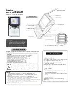
Off /Continuous /Automatic Selector Switch - 

The control switch is used to turn power to the generator on and off and to select 
the mode of operation desired.  Naturally, in the off position there is no power to 
the unit and the light inside the switch remains off. 

When the switch is turned one position to the right (so that it points straight up 
and down), the ‘Continuous’ mode has been selected and the unit will cycle 
regardless of whether or not oxygen is being drawn from the storage tank.  The 
light inside the switch will always be on as well.  The advantage to operating in 
this mode is that oxygen should be available at a slightly higher pressure than if 
in the automatic mode.  How much higher depends on the demand for it.  The 
disadvantage to operating in this mode is that your compressor will run more 
often. 

Turning the switch to the far right position puts the generator in the ‘Automatic’ 
mode.  In this mode a pressure switch is engaged to sense the oxygen storage 
tank pressure.  Once that pressure reaches about 60 PSIG (420 kPa) the 
generator will stop cycling.  When the pressure in the storage tank falls to about 
45 PSIG (310 kPa), the generator will begin to cycle again attempting to refill the 
storage tank.  While in this mode, the light inside the control switch will be on 
whenever the unit is cycling. 


Oxygen Pressure Gauge - 

This gauge indicates the pressure of the Oxygen in the storage tank.  While this 
level can vary between 0 PSIG and 65 PSIG (0 kPa and 450 kPa), it should 
remain between 40 PSIG and 65 PSIG (280 kPa and 450 kPa) during normal 
operation.  The exception, of course, is when the unit is first started and it needs 
to fill the storage tank.  This does not take more than a few minutes. 


Summary of Contents for OG-75

Page 1: ...814 Wurlitzer Drive North Tonawanda New York 14120 Telephone 716 564 5165 Fax 716 564 5173 Toll Free 800 414 6474 E mail ogsimail ogsi com Web Site http www ogsi com Model OG 75 thru OG 750 Oxygen Ge...

Page 2: ...onnection Diagram 14 Setup Instructions 15 16 Safety Precautions 17 Start Up Procedures 18 19 Shut Down Procedures 20 Troubleshooting Guide 21 Detailed Warning Description 22 Component drawings descri...

Page 3: ...2003 OGSI All rights reserved OGSI is a registered trademark This publication may not be reproduced in part or whole without written permission of OGSI...

Page 4: ...unit to the same degree that it was received from OGSI to ensure its undamaged arrival at OGSI If any damage is discovered during the initial visual inspection call the Freight Company immediately Th...

Page 5: ...which is Greenwich Mean Time minus 5 hours GMT 5 You may reach OGSI personnel through the following means By Telephone from within the United States two numbers may be used 800 414 6474 our toll free...

Page 6: ...ned from OGSI prior to return shipment of equipment These warranties shall also become null void and not binding on OGSI if a defect or malfunction occurs in the product or any part of the product as...

Page 7: ...combustible materials Precautions should be taken to avoid a fire in the area of the generator Smoking should not be permitted in the area where the generator is located All oxygen connections and hos...

Page 8: ...d not be removed except for active use Remember to replace removable caps when not in use Do not place cylinders in a position where they might become part of an electric circuit When electric welding...

Page 9: ...f the beds the sieve in that bed holds the Nitrogen to it and allows the Oxygen to flow through it and out to the surge tank as product gas Eventually the sieve becomes saturated with Nitrogen When th...

Page 10: ...183 775 351 OG 250 26 x 32 x 72 66 x 81 x 183 1100 499 OG 375 30 x 36 x 84 76 x 91 x 213 1350 612 OG 500 36 x 48 x 83 91 x 122 x 211 1800 816 OG 650 48 x 55 x 83 122 x 140 x 211 2400 1625 OG 750 38 x...

Page 11: ...ee of toxic gases and high concentrations of hydrocarbons especially carbon monoxide Additionally to the degree possible humid oily areas should be avoided as installation sites Ambient Air Temperatur...

Page 12: ...eep it from flowing into the generator Finally as already mentioned in a few areas the filter element inside the Oxygen Generator needs to be replaced every six months Electrical Power On U S models t...

Page 13: ...ted G 22 O I S G 22 G I OGS O I S G 22 G Occasionally a user may choose to maintain a liquid or cylinder backup and keep it connected to his system for critical applications This is a precaution that...

Page 14: ...making sure no empty voids are left in the beds The sieve can be harmed by exposure to air and caution must be taken to keep the sieve in the oxygen generator the container sealed as much as possible...

Page 15: ...Effective April 2006 12 Sieve Re packing Diagram...

Page 16: ...FRONT OF THE ENCLOSURE DOOR 3 NEXT TAKE 6 AND PUSH ONTO 1 FROM THE BACKSIDE OF THE ENCLOSURE DOOR 4 NOW HAND TIGHTEN 5 ONTO 1 FROM THE BACKSIDE OF THE ENCLOSURE DOOR 5 AFTER THIS PUSH 3 INTO 1 FROM TH...

Page 17: ...TCH ASSEMBLY INSTRUCTIONS 1 TAKE 1 AND PUSH THROUGH 4 2 NOW TAKE 1 4 AND PUSH THROUGH THE FRONT OF THE ENCLOSURE DOOR 3 PUSH 2 ONTO 1 AND TURN IT TO LOCK THEM TOGETHER 4 NOW MAKING SURE THE ASSEMBLED...

Page 18: ...or a male pipe thread depending on which model you have Connections to these are readily available worldwide through the Parker distribution network or from OGSI 3 Unroll and Direct the Filter Drain C...

Page 19: ...before this Oxygen Hose and Ball Valve are not included with the generator because the connections used from location to location can vary greatly We can provide these Ball Valves and Hose Assemblies...

Page 20: ...acility 2 Ensure that the oxygen outlet stream is not directed toward anyone s clothing Oxygen will embed itself in the material and one spark or hot ash from a cigarette could ignite the clothing vig...

Page 21: ...lown out the drain valve on the bottom of the cabinet If after 5 seconds air is not blowing out the filter drain then manually depress the filter drain push button on the lower left hand side of the c...

Page 22: ...cation This valve although not included in our standard accessory package should be in place to ensure a proper shut down and avoid the possibility of wasting oxygen through an improperly closed torch...

Page 23: ...tch to Off This should really only be done if the storage tank is already pressurized to at least 40 PSIG 280 kPa OR 2B Leave the Control Switch in the AUTO Position and Allow the Generator to Cycle U...

Page 24: ...high purity The following troubling shooting checks are for machines equipped with the optional Touchscreen Control system only System fails to start 1 If in manual mode press the additional start pu...

Page 25: ...set to 50 psig higher than the maximum setting for normal system operation High pressure transducer replacement will be necessary if this fault occurs Low Oxygen Pressure This may be a result of a lea...

Page 26: ...Effective April 2006 23 Process Flow Schematic...

Page 27: ...Effective April 2006 24 Process Flow Schematic Touchscreen Option...

Page 28: ...is directed into one of the two sieve beds As the air enters the bed the nitrogen is adsorbed by the sieve and the oxygen passes through as product gas Each bed produces Oxygen until the sieve in that...

Page 29: ...Effective April 2006 26 External Components Drawing 22 G G 22...

Page 30: ...of whether or not oxygen is being drawn from the storage tank The light inside the switch will always be on as well The advantage to operating in this mode is that oxygen should be available at a slig...

Page 31: ...ort circuiting either a fuse or circuit breaker depending on which model you have Generators shipped outside North America will have an electrical plug suitable for use in the location to which it is...

Page 32: ...you should attach to it It can be used to set the regulated Oxygen pressure out of the storage tank at any level up to 60 PSIG 420 kPa Please keep in mind that our specification for the maximum oxyge...

Page 33: ...Effective April 2006 30 Internal Components Drawing SMC SMC Direct 05 LOGIC Koyo SMC...

Page 34: ...henever the Feed Valve on the A side of the machine is open the Waste Valve on the B side will also be open The reverse is also true Drain Valve The Drain Valve allows condensate and waste material tr...

Page 35: ...he hours meter increments time while the unit is running It provides an indication as to when service intervals are due Noise Muffler The noise muffler is used to silence the exhaust noise that occurs...

Page 36: ...quest The next screen is the Control Screen This screen contains the modes of operation and indicator buttons For the machine to start cycling one of the Mode of Operation Buttons must be selected eit...

Page 37: ...een contains a graph of the 4 gauges over time Every five minutes a reading is taken The legend on the bottom of the screen contains the coordinating colors of the meters The Alarm Screen contains 7 t...

Page 38: ...ow Area If you want SPANISH as your default language touch anywhere in the Yellow Area Once a language has been chosen press this button to advance to the next screen If you want ENGLISH as your defau...

Page 39: ...apping the password area titled Enter Numeric Entry When this appears enter your numeric password given to you by OGSI Note The user will not be allowed to change their default password so keep it sec...

Page 40: ...TATUS represents the Generator having proper supplied power The Indicator Button CONTINUOUS MODE represents if CONTINUOUS is selected in the main control If any other option is selected on the MAIN CO...

Page 41: ...rator is in STANDBY MODE meaning the Pressure switch has gone active meaning the machine is NOT Cycling but the Generator is still in Automatic Mode The Indicator Button CYCLING represents if the gene...

Page 42: ...ic Mode Simply touch any where in the green area and a numeric keypad will appear to enter the low point Only 2 digits can be placed into the keypad Some limitations are in the top right corner of the...

Page 43: ...creasing it one hour accordingly You may adjust the REALTIME CLOCK by decreasing it one hour accordingly If you want to go back to the Previous Screen Control Screen all you have to do is touch the Bl...

Page 44: ...e except for the normal operating variance that is between 0 and 20 psi This Meter OXYGEN PRESSURE measures the Oxygen Pressure psig in your back pressure regulator The same details hold true for this...

Page 45: ...clear the readings and if the generator is not cycling you can stop the graph from reading Using the CLR and Stop Buttons Also you can scroll through the graph using the 4 buttons in the upper left co...

Page 46: ...is above 80 psi This particular alarm is triggered when the Oxygen Pressure is below 40 psi This particular alarm is triggered when the Oxygen Pressure is above 65 psi This particular alarm is trigger...

Page 47: ...ril 2006 44 If you want to go back to the Previous Screen Pressure Screen all you have to do is touch the Blue Area If you want to advance to the Next Screen Final Screen all you have to do is touch t...

Page 48: ...GE purity of your OGSI Generator This is the date that your machine was shipped General Information If you want to go back to the Previous Screen Alarm Screen all you have to do is touch the Blue Area...

Page 49: ...Effective April 2006 46 Manifold Drawing...

Page 50: ...Oxygen under high pressure is present The use of safety glasses and hearing protection is required Slowly disconnect the steel whip from the cylinder valve using a 1 1 8 wrench Be aware of the ventin...

Page 51: ...long runs condensation inside the pipes can be a big problem The solution is to have traps and drains opened regularly automatically if practical to keep the water from reaching your Oxygen Generator...

Page 52: ...to pull it out of the fitting the collar of the Prestolok fitting is probably not being pushed back into the fitting hard enough The tube should come out easily once it is released from the fitting 7...

Reviews: