


Board Control and Status Registers (BCSRx)
MSC711x Application Development System (MSC711xADS) Reference Manual, Rev. 1
Freescale Semiconductor
31
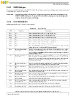
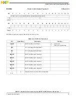
BCSR0 is accessed at offset 0x0 from the BCSR base address. BCSR0 gets its defaults at power-on reset.
BCSR0
Board Control Status Register 0
Offset 0x0
Bit
0
1
2
3
4
5
6
7
8
9
10
11
12
13
14
15
PQETHEN PQETH
RST
PQRSEN CONFEN Bootp
—
GPLLED0 GPLLED1
—
TYPE
R/W
R
R/W
R
RESET
0
1
1
1
1
0
1
1
Bit
16
17
18
19
20
21
22
23
24
25
26
27
28
29
30
31
—
TYPE
R
RESET
0
0
0
0
0
0
0
0
0
0
0
0
0
0
0
0
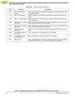
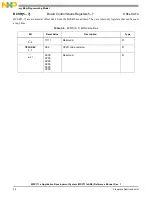
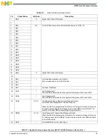
Table 4-1. BCSR0 Bit Descriptions
Bit
Reset Value
Description
Settings
PQETHEN
0
0
MPC8272 Ethernet enable.
0 Disabled.
1
Enabled.
PQETHRST
1
1
MPC8272 Ethernet reset.
1 Deasserted.
0 Asserted.
PQRSEN
2
1
MPC8272 RS-232 transceiver enable.
1
Disabled.
0
Enabled.
CONFEN
3
1
MPC8272 Hard Reset Configuration Word
source.
0
Flash memory.
1
BCSR.
Bootp
4
1
Flash boot sector write protect:
0 Protect.
1 Do
not
protect.
5
Reserved. Write to zero for future compatibility.
GPLLED0
6
1
General-purpose LED 0.
0 ON.
1 OFF.
GPLLED1
7
1
General-purpose LED 1.
0
ON.
1 OFF.
—
8–31
Reserved. Write to zero for future compatibility.