


MSC711x Application Development System (MSC711xADS) Reference Manual, Rev. 1
10
Freescale Semiconductor
Hardware Configuration and Boot
7.
Establish the appropriate external connections (for a list of external connections and their locations,
see Figure 1-2 on page 5).
8.
Turn on the MSC711xADS voltage (SW9, as shown in Figure 1-2 on page 5). Note that ON is up and
OFF is down. We recommend that you turn off the voltage if the MSC711xADS is unused for more
than 48 hours.
2.3 Board Configuration
The MSC711xADS can be installed for either host-controlled or stand-alone operation. In host-controlled
operation, the MPC8272 and the MSC711x processors are both controlled by a host computer and are connected
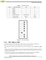
via a separate JTAG chain or a shared JTAG chain. Use the SW6 switch to configure the MSC711xADS JTAG
options (see Section 2.4.4):
• Separate chain. The MPC8272 and the MSC711x processors each independently connects to a JTAG command
converter. The MPC8272 connects via the JTAG/COP connector (P14) to a JTAG command converter or
through the parallel port connector (P11) to a PC and does not use an external JTAG command converter. The
MSC711x can directly connect through the JTAG/OCE10 connector (P8) via a JTAG command converter.
• Shared chain. Both the MPC8272 and MSC7116 processors share the same JTAG chain. The MPC8272 is the
first device in the chain, so either the JTAG command converter connects to it via the JTAG/COP connector
(P14) or it connects to a PC through the parallel port connector (P11) with no use of an external JTAG command
converter. The debugging tool must support the shared JTAG chain option, as CodeWarrior does.
In stand-alone operation, the host computer controls the MSC711xADS board not through the JTAG port but
through one of its other ports, such as the RS-232 port or the fast Ethernet port. The application program must be
programmed into the board Flash memory for the MPC8272 and into the board I
2
C EEPROM for the MSC7116.
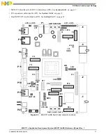
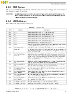
2.4 DIP-Switch and Jumper Settings
To select the desired configuration and ensure proper operation of the MSC711xADS board, you may have to
change the DIP-Switch settings before installation. The location of the switches, indicators, DIP-Switches, and
connectors is illustrated in Figure 2-1. The board has been factory tested and is shipped with DIP-Switch settings
as described in the following paragraphs. Values can be changed for the following parameters:
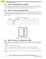
• MSC711x internal voltage supply level via potentiometer (RP1). See Section 2.4.1 on page 12.
• MSC711x power-up configuration (SW4). See Section 2.4.2 on page 12.
• MSC711x event pin configuration (SW5). See Section 2.4.3 on page 12.
• JTAG options (SW6). See Section 2.4.4 on page 13.
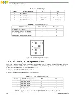
• Select I
2
C EEPROM address and protection mode (SW7). See Section 2.4.5 on page 14.
• MPC8272 clock mode settings (SW8). See Section 2.4.6 on page 15.
• Main power switch (SW9). See Section 2.4.7 on page 15.
• MSC711x Ethernet PHY MII/RMII mode (JP1). See Section 2.4.8 on page 15.
• H110 back plane reset (JP2). See Section 2.4.9 on page 16.
• TDM master selection (JP3). See Section 2.4.10 on page 16.
• MSC711x clock-in source (JP4). Section 2.4.11 on page 16.
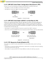
• MPC8272 Hard Reset Configuration Word source (JP5). Section 2.4.12 on page 17.