Battery Stack and DC Bus
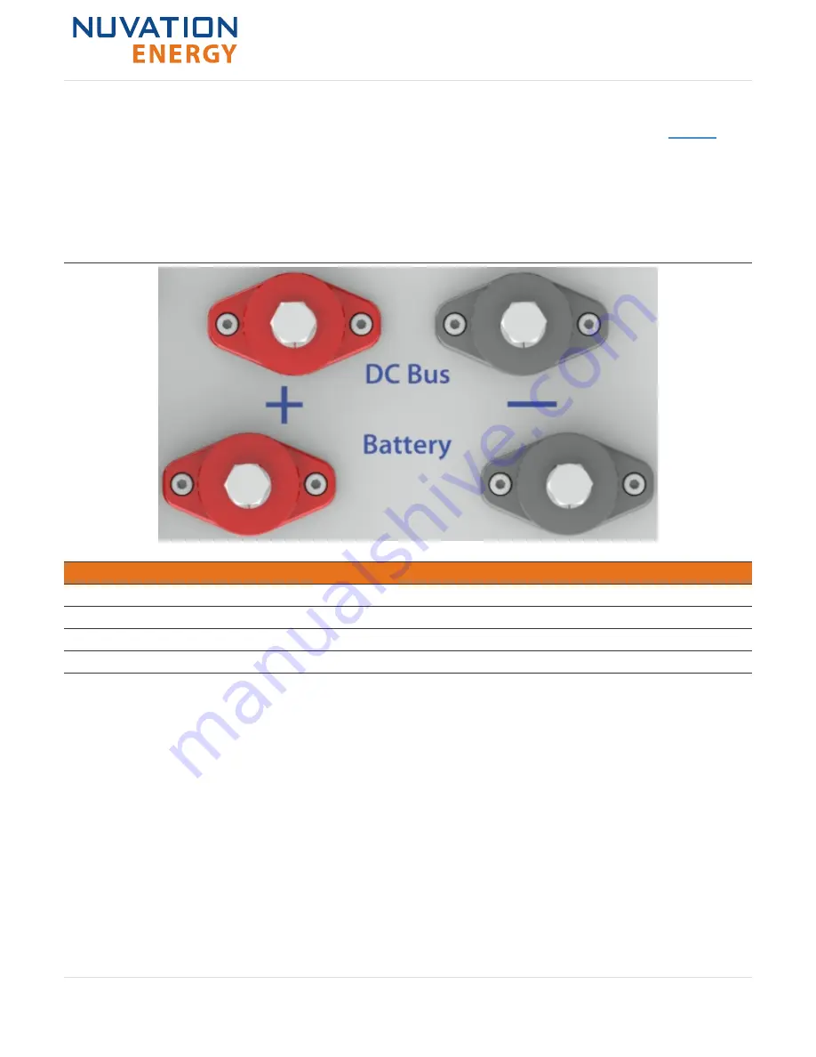
The front panel of the Stack Switchgear has four high power connectors, as illustrated by
. Two
of these are for the positive and negative terminals of the battery stack; the other two are for the
connection to the DC bus (or a power conversion system in a single stack system). The colors are
coordinated such that red is for the positive connections and black is for the negative connections.
The connectors use M8 screws (included) and are intended for M8 lugs (not included, e.g. Panduit
Corp LCMA50-8-L). Flexible snap-on terminal covers are included.
Table 9. High power connections
Name
Description
Connected to Device
Battery (-)
Negative terminal of battery stack
Battery stack
Battery (+)
Positive terminal of battery stack
Battery stack
DC Bus (-)
Negative terminal of DC bus
External equipment
DC Bus (+)
Positive terminal of DC bus
External equipment
In order to make the connection:
1. Feed the wire through the terminal cover
2. Strip the insulation
3. Crimp the lug
4. Screw the lug onto the terminal
5. Slide the terminal cover onto the terminal
The recommended tightening torque is 5.7 to 6.8 N-m [50 to 60 in-lbs].
Nuvation Energy Stack Switchgear - Product Manual
Document ID: NE-PM-003
24
Rev 1.0, 2020-09-03


