LinMot Installation Guide
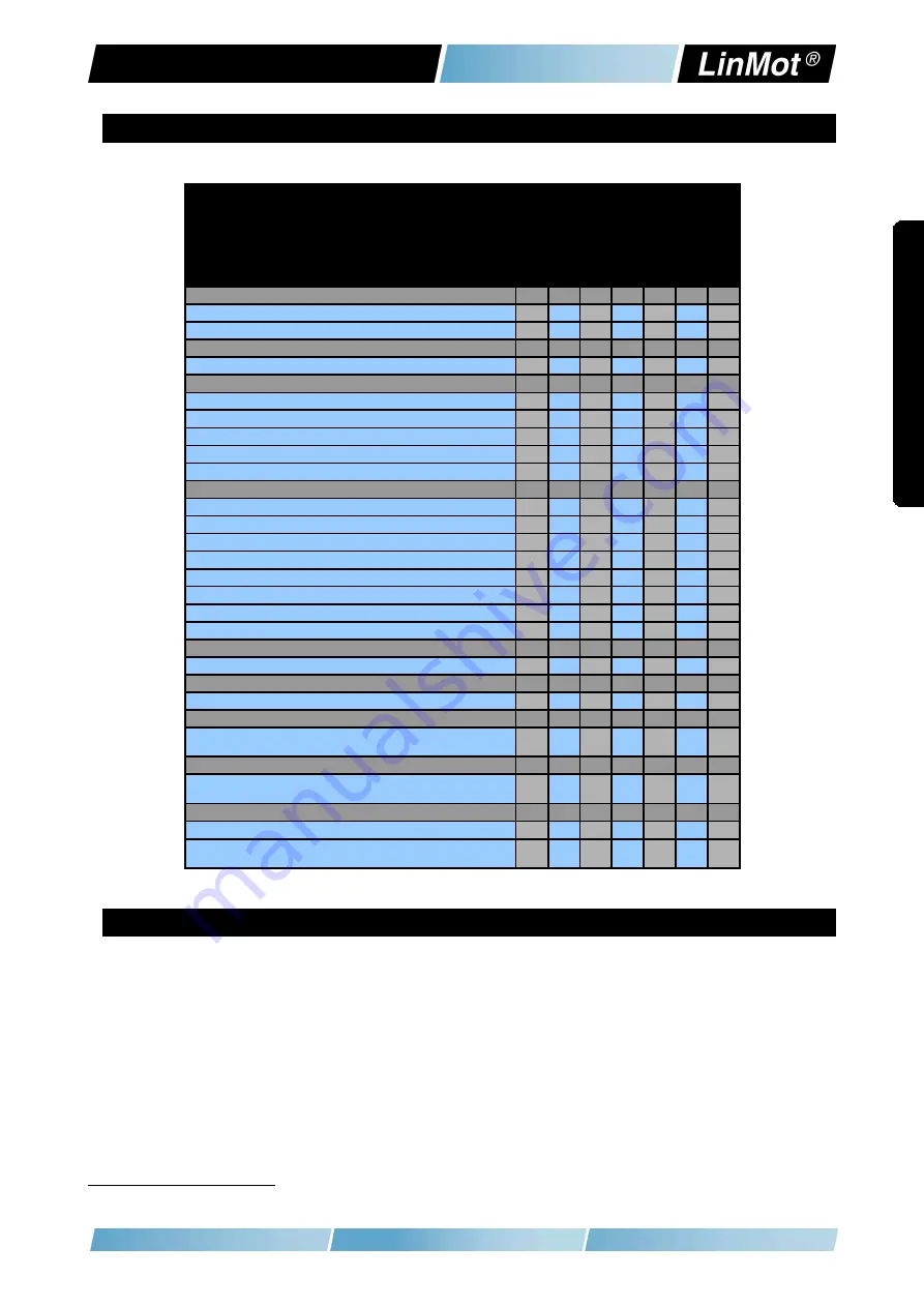
3 Functionality and Interfaces
E
1
25
0
-P
L
-U
C
E
1
25
0
-P
N
-U
C
E
12
50
-S
C
-U
C
E
1
25
0
-I
P
-U
C
E
1
25
0
-E
C
-U
C
E
1
23
0
-D
P
-U
C
E
1
20
0
-G
P
-U
C
Supply Voltage
Motor Supply 72VDC (24...85VDC)
●
●
●
●
●
●
●
Logic Supply 24VDC (22...26VDC)
●
●
●
●
●
●
●
Motor Phase Current
32A
peak
/ 12A
rms
●
●
●
●
●
●
●
Controllable Motors
LinMot
P01-23x… (Motor Link P)
●
●
●
●
●
●
●
P01-37x… (Motor Link P)
*
●
●
●
●
●
●
●
P01-48x… (Motor Link P)
*
●
●
●
●
●
●
●
DC Motors
●
●
●
●
●
●
●
Brushless DC / EC Motors
●
●
●
●
●
●
●
Command Interface
CANopen
●
●
●
●
●
●
●
LinRS
●
●
●
●
●
●
●
POWERLINK
●
PROFINET
●
SERCOS III
●
ETHERNET IP
●
ETHERCAT
●
PROFIBUS-DP
●
Programmable Motion Profiles (Curves)
Up to 100 Motion Profiles
●
●
●
●
●
●
●
Programmable Command Table
Command Table with up to 255 entries
●
●
●
●
●
●
●
External Position Sensor
Incremental
(RS422 up to 25 M counts/s, quadrature ev.)
●
●
●
●
●
●
●
Synchronisation
Master Encoder In/Out
(RS422 up to 25 M counts/s, quadrature ev.)
●
●
●
●
●
●
●
Configuration Interface
RS232
●
●
●
●
●
●
●
Ethernet 10/100 Mbit/s
(2-Port Switch integrated)
●
●
●
●
●
●
●
4 IP Address Selection
The default mode for acquiring an IP address is via DHCP. If no servers respond on
the connected network, the controller switches to the Ipv4 Link-Local addressing
scheme (also known as APIPA on Windows systems). This way the controller
automatically assigns itself an address within the range of 169.254.0.1 through
169.254.255.254 (Subnet Mask 255.255.0.0).
Please note that this process can take up to a minute until a valid address is
assigned to the controller.
* LinMot Motor Communication
NTI AG / LinMot
®
www.LinMot.com
Page 6/20
E
1
2
0
0
In
s
ta
lla
ti
o
n
G
u
id
e


