background image

© 2022 Genesis Attachments, LLC

Genesis GXT Mobile Shear

32

GENERAL OPERATION INSTRUCTIONS

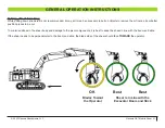
Pushing / Tracking Forward

When pushing material, it is best to keep the shear in line with the boom and stick.

If the shear needs to be perpendicular to the boom and stick, the blade side of the shear should face 

AWAY

 from the operator.

OK

Best

Best

Blades Away

from the Operator

Shear is In Line with the

Excavator Boom and Stick

Summary of Contents for Genesis GXT 665R

Page 1: ...GXT Mobile Shear SAFETY OPERATOR S MANUAL...

Page 2: ...mail tchoo genesisattachments com Europe Africa Middle East Genesis GmbH Teramostrasse 23 87700 Memmingen Germany Phone 49 83 31 9 25 98 0 Fax 49 83 31 9 25 98 80 genesis europe com E mail info genes...

Page 3: ...ments com manuals Registration Form The Warranty Registration Form must be filled out by the dealer or customer and returned to Genesis indicating the date the attachment went into service Possible Va...

Page 4: ...Power Lines 12 Use Care with Hydraulic Fluid Pressure 13 Prioritized Oil Flow 14 Emergency Situations 14 Unsafe Conditions 14 Crystalline Silica Dust 14 Process Material Safely 15 Lift the Load Safel...

Page 5: ...TS 38 BOLT TORQUE SPECS 39 BLADE MAINTENANCE 40 AUTOGUIDE 41 AutoGuide Adjustment Procedure 41 PIERCING BLADES 42 Replacement 44 GUIDE BLADES 45 Shimming 45 Rotation 46 Replacement 46 Adjustment Plate...

Page 6: ...x Lube Change out Procedure 63 ROTATION WITH CROSSOVER RELIEF VALVE 64 Setting the Crossover Reliefs 64 ROTATION WITH MOTION CONTROL VALVE 65 TROUBLE SHOOTING GUIDE 66 WARRANTY 69 Claim Procedure 69 B...

Page 7: ...sult in injury or death This statement is used where serious injury or death could result if the instructions are not followed properly WARNING This statement is used where minor or moderate injury co...

Page 8: ...e and replace any damaged or worn parts Before Operating 3 Warn all others in the area that you are about to start operation 3 Perform the Check the Equipment steps outlined in this manual 3 Check und...

Page 9: ...etaining bolts 3 Check cylinders for dents barrel or dings rod GOOD CONDITION P WARNING Serious injury or death could result if warnings or instructions regarding carrier stability and the work area a...

Page 10: ...least 75 feet away from the area of operation and equipment movement Let all other workers and bystanders know you are preparing to start DO NOT operate until everyone is clear Always be properly seat...

Page 11: ...lls ridges banks and slopes Avoid operating across a slope which could cause the carrier to overturn 3 Reduce speed when driving over rough terrain on a slope or when turning to avoid overturning the...

Page 12: ...g Falling Object Protection Structures or FOPS are necessary for any application where material is to be handled overhead Transporting the Attachment 3 Travel only with the attachment in a safe transp...

Page 13: ...njected fluid see a doctor immediately 3 Wear safety glasses and protective clothing and use a piece of cardboard or wood when searching for hydraulic leaks Do Not Use Your Hands See illustration belo...

Page 14: ...rations or high reach conditions Emergency Situations Always be prepared for emergencies Make sure a fire extinguisher is available Be familiar with its operation Make sure to inspect and service the...

Page 15: ...s as the release of compressed springs is extremely dangerous Nothing made of spring material or containing springs should be processed Lift the Load Safely The hydraulic system has been preset and te...

Page 16: ...2022 Genesis Attachments LLC Genesis GXT Mobile Shear 16 SHEAR NOMENCLATURE 4 5 6 8 9 10 12 14 1 2 3 7 11 13 15 16 17 18 19 20 10 11 21 22...

Page 17: ...ote From the operator s view the left guide blade may or may not have an adjustment plate If not insert shim s directly against the back of the guide blade 13 Secondary Blades Upper and lower cutting...

Page 18: ...ved before operating the attachment to prevent rotation system damage The rotation locks are located inside the small bolt covers for the slewing ring and marked with a red flag labeled REMOVE ROTATIO...

Page 19: ...ding on whether the bucket and auxiliary are on separate sides of the main valve and whether the auxiliary circuit can be proportionally controlled by teeing into the bucket pilot control circuit The...

Page 20: ...ower link bore lines up with the cylinder pivot connection Pin the excavator cylinder to the attachment Crowd and extend the attachment checking closely to make sure there is no interference between t...

Page 21: ...during cold weather operation Use the correct fittings Secure the case drain line to the excavator stick Do not plumb the case drain into the main return system or into any other existing case drain o...

Page 22: ...em center spring centered with anti cavitation checks Port relief settings 2000 PSI 7 Case Drain Use minimum 1 2 250 PSI rated hose to dedicated filter Do not plumb the case drain into the main return...

Page 23: ...SI rated hose 6 Auxiliary Valve 3 position tandem center spring centered with anti cavitation checks Port relief settings 2000 PSI 7 Case Drain Use minimum 1 2 250 PSI rated hose to dedicated filter D...

Page 24: ...tion Valve Gerotor Motor 1 Gerotor Motor 2 Motion Control Valve 3 Flow Controls 4 Rotate Work Lines Use 1 2 3000 PSI rated hose 5 Auxiliary Valve 3 position tandem center spring centered with anti cav...

Page 25: ...tion Control Valve 3 Flow Controls 4 Rotate Work Lines Use 1 2 3000 PSI rated hoses 5 Rotation Valve 3 position tandem center spring centered with anti cavitation checks Port relief settings 2000 PSI...

Page 26: ...ted hose 6 Rotation Valve 3 position tandem center spring centered with anti cavitation checks Port relief settings 2000 PSI 7 Case Drain Use minimum 1 2 250 PSI rated hose to dedicated filter Do not...

Page 27: ...ols 5 Rotate Work Lines Use 1 2 3000 PSI rated hose 6 Auxiliary Valve 3 position tandem center spring centered with anti cavitation checks Port relief settings 2000 PSI 7 Case Drain Use minimum 1 2 25...

Page 28: ...e OEM procedures for starting and warming the excavator hydraulic system Do not operate the shear circuit during the warm up period 3 After the excavator has reached normal operating temperature set t...

Page 29: ...When cutting build up and cut out of small piles keeping the surfaces of the shear chin plate and upper jaw out of the dirt as much as possible Dirt is much more abrasive than steel and needlessly in...

Page 30: ...s the blades and parent material of the jaws are subject to thermal expansion from cutting friction The tighter the blades run the hotter they get and the more they expand Piercing blades and guide bl...

Page 31: ...to remove them from a pile or better position pieces to be cut To minimize stress in the shear body and damage to the pivot components it is best to keep the shear in line with the boom and stick If t...

Page 32: ...orward When pushing material it is best to keep the shear in line with the boom and stick If the shear needs to be perpendicular to the boom and stick the blade side of the shear should face AWAY from...

Page 33: ...ed in a pile has a resistance to movement that causes undo stress in the shear body when you try to cut it This stress occurs in both straight and rotating units because the shear will work to align i...

Page 34: ...d durability of the shear and may void the warranty Follow the daily checklist and maintenance schedules in this manual Extreme conditions may dictate shorter maintenance intervals Do not exceed bolt...

Page 35: ...ore welding or heating Hazardous fumes dust can be generated when paint is heated by welding soldering or using a torch Do all work outside or in a well ventilated area and dispose of paint and solven...

Page 36: ...uses undue pressure on the wear bands of the piston potentially resulting in cylinder failure Pounding the upper jaw lever arm or cylinder clevis on the ground or a hard object to clear a material jam...

Page 37: ...r leaks Bracket pivot for wear and pin retainers Cylinder pivot for wear and pin retainers Entire shear for cracks visual check Grease Bracket pivot Bracket cylinder Bearing slewing four locations All...

Page 38: ...ratures below 32 F use a grade 0 grease Do not use grease containing Molybdenum Moly Genesis GLG 2 anti wear extreme pressure lithium grease PN 6302601 is recommended for all temperature conditions Th...

Page 39: ...2022 Genesis Attachments LLC Genesis GXT Mobile Shear 39 BOLT TORQUE SPECS Bolt torque specs and thread treatment procedures can be found in the Genesis Fastener Manual genesisattachments com manuals...

Page 40: ...Secondary Blades rotate shim to tolerance and replace when all edges are worn All four blades are identical on shears featuring dual guide blades 5 Razor Blade rotate and replace when worn 6 Jaw Hard...

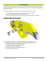
Page 41: ...0 010 3 Check tolerances every eight hours of operation and shim as needed 3 Never overtighten the puck against the wear surface 3 Perform puck maintenance and shimming before performing blade mainte...

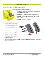
Page 42: ...th a straight edge or square 4 Check the profile along the blades 5 Badly worn blades must be replaced However slightly worn blades may be squared up with a grinder and a square This may be repeated u...

Page 43: ...that the piercing blade pocket and tang surfaces are straight and true without dings deformations high or low spots or areas that are worn away Piercing blade bolts must not make hard contact with the...

Page 44: ...e seats 8 With a feeler gauge confirm there is a gap where the blades meet Gap width by model is shown below the graphic to the right A very narrow gap may be confirmed by shining a flashlight from be...

Page 45: ...st applications it is beneficial to maintain a wider gap at the guide blades Shimming Slowly close the jaw so the upper piercing blades begin to bypass the guide blades Stop the jaw and check the gap...

Page 46: ...each shear and need only be replaced when lost damaged or extremely worn Inspect the top of the adjustment plate for burrs nicks or other imperfections that may prevent proper seating of the guide bla...

Page 47: ...cutting edges Always use Genesis approved blades Blades that do not meet Genesis specifications can cause major problems and using them may void the warranty Before performing any blade maintenance r...

Page 48: ...g an extra set on hand to reduce downtime Offset dowel or fastener holes are located in each adjustment plate When replacing adjustment plates make sure these holes are aligned with the corresponding...

Page 49: ...will be consistent along the entire length of the blades if they have been rotated and shimmed correctly If the blade gap exceeds the maximum listed on the table above shim the lower blades Blades mus...

Page 50: ...he illustration After rotation check the gap between the razor blade and piercing blades If the gap exceeds the maximum tolerance after new piercing blades have been installed the razor blade must be...

Page 51: ...p Disconnect all battery ground cables or shut off master battery switch if equipped Failure to do so may cause excavator electrical problems including permanent damage to onboard computer systems Con...

Page 52: ...r than blade height These areas protect the bottom unused edges of the blades as well as reduce the chance for material to catch on the bottom of the blade during jaw open functions which causes blade...

Page 53: ...n with the grain using E7018 electrode Peen each pass Do not apply a stringer directly on the edge Start the first pass 1 4 from the edge Stagger the ends of the stringer welds so they do not end in a...

Page 54: ...es approximately 1 apart Begin just behind the piercing blade seats and continue toward the throat Use three to five stringers depending on the shear model Staggered stringers Grain Lower Jaw Single p...

Page 55: ...as indicated in the chart below The maximum case drain measured at the shear while rotating and cycling the jaws must never exceed 80 PSI Pressure increases during cold weather operation Model Flow P...

Page 56: ...cut is complete The cartridge is factory set turned out approximately seven turns This setting is appropriate for most applications However the cartridge may be custom set if necessary Contact Genesis...

Page 57: ...s to test cut This must be heavy enough for the shear to shift into the power mode 9 If you are not operating the shear maintain a safe distance of at least 75 ft from the operating shear 10 Close the...

Page 58: ...nd speed it results in pressurized fluid on the rod side If left in this mode cylinder power is greatly reduced Jaw Close in Power Mode To provide full power when the upper jaw hits the material the p...

Page 59: ...54 486 ft lbs 616 659 Nm Pilot Check Valve 6380088 Seal Kit SK00024 Directs oil from rod to bore in speed mode blocks oil path between rod and bore in power mode Torque to 454 486 ft lbs 616 659 Nm Ch...

Page 60: ...659 Nm Pilot Check Valve 6380088 Seal Kit SK00024 Directs oil from rod to bore in speed mode blocks oil path between rod and bore in power mode Torque to 454 486 ft lbs 616 659 Nm Pressure Reducing V...

Page 61: ...ects oil from rod to tank in power mode blocks oil path from rod to tank in speed mode Torque to 454 486 ft lbs 616 659 Nm Pilot Check Valve 6380088 Seal Kit SK00024 Directs oil from rod to bore in sp...

Page 62: ...the attachment to break free which may result in serious personal injury and equipment damage Improper torque will also cause uneven slewing ring wear Rotating components must be greased daily Grease...

Page 63: ...s Gearbox Lube Change out Procedure 1 Position the shear so the gearbox is horizontally level at a convenient working height 2 Remove the rotator access cover and place an oil drain pan under the gear...

Page 64: ...ossover Reliefs 1 Increase supply pressure to the rotation valve to 2500 PSI 2 Install pressure gauges on relief test ports 3 Plug hoses at motor or secure the shear from rotating 4 Pressurize the val...

Page 65: ...turns so they can later be returned to their original setting Adjust the counterbalance valves by turning the adjustment screws counter clockwise until the correct setting of 2500 PSI is reached Repe...

Page 66: ...can be pushed closed Regen bleed down orifice may be plugged Regen pilot check valves may be leaking Directional valve on excavator may be leaking Jaw closes suddenly and will not open Ball valve may...

Page 67: ...e Regeneration Valve section of manual Shear swivel or cylinder is bypassing contact the Genesis Service Department for procedures to check for bypass Poor Piercing Piercing tips are worn and need to...

Page 68: ...while actuating foot switch in both directions Rotator chatters Electrical short back out flow controls Pressure settings too high reset Power to both rotation solenoids at the same time test for 24V...

Page 69: ...mit an invoice to the Genesis Service Department within 30 days Include itemized internal labor reporting parts lists and invoices for outside contractors Reference the authorization number on all inv...

Page 70: ...h invoices open beyond 60 days are subject to review and may be placed on C O D status without further notice Returns Most unused Genesis parts may be returned with proper documentation Return shippin...

Page 71: ...ORM E mail to the Genesis Parts Department genesisparts genesisattachments com For assistance call 715 395 5252 Customer Phone Shipping Address Purchase Order Model Date Contact E mail Billing Address...

Page 72: ...enesis europe com E mail info genesis europe com Central America Colombia Cra 13A 89 38 Ofi 613 Bogota Colombia Phone 57 1 610 8160 795 8747 E mail contact themsagroup com Genesis Attachments 1000 Gen...

Reviews: