Norwood The Grain Handler 10 Operator'S Manual Download Page 119

8 - FORMS AND DECLARATIONS

8-1

8 - FORMS AND DECLARATIONS

Norwood Sales Inc. follows the general Safety Standards specified by the American Society of Agricultural and Biological 

Engineers (ASABE

®

), and the Occupational Safety and Health Administration (OSHA

®

). Anyone who will be operating and/

or maintaining the equipment must read and clearly understand all Safety, Operating and Maintenance information presented 

in this manual.

Do not operate, or allow anyone else to operate, this equipment until this document has been read. Review this information 

annually, before the season start-up.

Make periodic reviews of SAFETY and OPERATION a standard practice for all of your equipment.

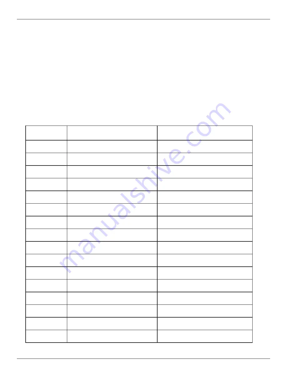
The following Sign-Off Form is provided for your record keeping. Use it to show that all personnel who will be working with 

the equipment have read and understand the provided information. Also, they have been instructed in the operation of the 

equipment. Copy this page to continue the record.


SIGN - OFF FORM

DATE

EMPLOYEES SIGNATURE EMPLOYERS SIGNATURE 

Summary of Contents for The Grain Handler 10

Page 1: ...U Trough Power Sweep Operator s Manual Models 8 10 U Trough Power Sweeps Sizes 18 19 21 24 27 30 33 36 42 48 54 60 Optional Equipment Kwik Belt Top Drive Field Loader Model 1843 The Grain Handler U T...

Page 2: ...Accessories 8S WR 3 Larger Capacity Non Leaking Transition Larger Capacity Non Leaking Transition Controlled Vertical Discharge Flow Controlled Vertical Discharge Flow Larger Heavy Duty PEER Bearings...

Page 3: ...ssociated with this machine as well as in all on product warning decals Failure to do so could result in death or serious injury or property damage Contact your Norwood dealer if any of your manuals a...

Page 4: ...a Vertical Wall of Grain 2 6 Flowing Grain 2 6 Grain Bin Safety Contd 2 7 Grain Bin Entry Safety 2 7 Roof Entry 2 7 Lock Out Tag Out Safety 2 7 Non Permissible Use 2 7 General Maintenance Safety 2 8 R...

Page 5: ...peration 4 7 Before Filling the Bin with Grain 4 7 Machine Placement 4 8 Emptying the Grain Bin 4 8 Unload Grain From the Center Sump 4 9 Unload Grain From the Intermediate Sumps 4 10 Unload Grain wit...

Page 6: ...5 Replacing the Drive Belts 5 15 2500 Hours Or Annually 5 16 Change Gearbox Oil 5 16 STORAGE 5 17 6 0 TROUBLESHOOTING 6 1 Troubleshooting Field Problems 6 1 Troubleshooting Field Problems Cont 6 2 Tro...

Page 7: ...um performance it is imperative that this machine is operated in accordance with the procedures outlined in this manual 1 0 GENERAL INFORMATION Note to the Owner This manual contains important informa...

Page 8: ...1202 38th St S Horace ND 58047 P N 10 5 000 07 Th e Gr ain Ha nd ler U Tr ou gh Po we r Sw ee p Op er ator s Ma nu al Mo del s 8 10 U T rou gh Pow er Sw eep s Siz es 18 19 21 24 27 30 33 36 42 48 54 6...

Page 9: ...he lines provided Model Number _________________________________ Date Of Purchase _______________________________ The Model Number for the Inclined Powerhead is iden tified in the following figure See...

Page 10: ...Locating Serial Number Decal Buzzwheel Make a copy of the serial number below and keep it in a safe place If the machine is stolen report the numbers to your local law enforcement agency Write the Se...

Page 11: ...the manual are determined when standing at the discharge end and looking at the intake end toward the center of the grain bin 4 2 3 1 Fig 1 9 Determining Left and Right Side of the Machine Determining...

Page 12: ...1 6 1 GENERAL INFORMATION This Page Is Intentionally Left Blank...

Page 13: ...ed with CAUTION on the machine decals is YELLOW FAILURE TO FOLLOW DANGER WARNING AND CAUTION MESSAGES COULD RESULT IN DEATH OR SERIOUS INJURY Machine Safety Informational NOTICE Notice or Note indicat...

Page 14: ...Additional safety messages are used in the text of the manual to indicate specific safety hazards See your dealer for more information if you have any questions Some illustrations in this manual will...

Page 15: ...ight ing 8 Have a qualified electrician provide power to the unit 9 Do not operate machine when any guards are removed 10 Stage the equipment away from overhead obstructions and power lines during ope...

Page 16: ...d grain may collapse under the weight of a worker trapping the worker in the grain and causing suffocation and death Sometimes looks can be deceiving Grain will crust over and look solid but a cavity...

Page 17: ...emoving Grain Dust With The Norwood Kwik Kleen Control the Ignition Source Where applicable use an electric motor rated for the dust classification area Do Not smoke inside or near the grain bin Use o...

Page 18: ...ring it with a rope in case it is dropped Be aware that chunks of crusted grain can move down to the auger and limit flow Collapse of a Vertical Wall of Grain Vertical walls of grain are created when...

Page 19: ...to make it flow FAILURE TO HEED THE WARNINGS ABOVE AND ENTER THE GRAIN BIN MAYCAUSE SERIOUS INJURYOR DEATH Roof Entry The information in this section applies to entry through the bin roof only Never...

Page 20: ...0 Chock wheels on towed implements that are staged with the Power Sweep Remove Paint Before Welding or Heating Avoid potentially toxic fumes and dust Hazardous fumes can be generated when paint is hea...

Page 21: ...cautiously under overhead power lines and around utility poles Know the transport height of all your equipment Electrocution can occur without direct contact with overhead electrical lines Electrical...

Page 22: ...ives Do not burn contaminated fuels and or waste oils in ordinary heating systems Avoid spillage when draining off used gearbox and hydraulic oils etc Do not mix drained fluids with lubricants Store d...

Page 23: ...reservoirs and lines before recycling compo nents Use leak proof containers when draining fluids Do not use food or beverage containers Do not pour waste fluids onto the ground down a drain or into an...

Page 24: ...WORK AREA AUTHORIZED PERSONNEL ONLY KEEP OUT OF SHADED HAZARD AREA OVERHEAD WIRES KEEP AWAY WHEEL CHOCKS WHEEL CHOCKS CONVEYOR INTAKE AREA KEEP OUT UNDER CONVEYOR AND UNDERCARRIAGE AREA KEEP AWAY WALK...

Page 25: ...5 1 4 6 Item Part Number Description Qty Item Part Number Description Qty 1 90 44 0582 Decal Warning Safety Information Power Sweep 1 7 90 44 0359 Decal Rotating Auger Hazard Keep Away 3 2 90 44 0011...

Page 26: ...to comply could result in death or serious injury Item Part Number Description Qty Item Part Number Description Qty 1 90 44 0582 Decal Warning Safety Information Power Sweep 1 8 90 44 0359 Decal Rota...

Page 27: ...and result in serious injury death or property damage NEVER ENTER A BIN WHEN IT IS BEING LOADED OR UNLOADED IF YOU MUST ENTER THE BIN YOU MUST DO THE FOLLOWING Shut off and lock out all power Use a sa...

Page 28: ...2 12 Safety Decal P N 90 44 0011 Qty 2 Fig 2 13 Safety Decal Location See Fig 2 12 NEVER ENTER BIN UNLESS ALL POWER IS LOCKED OUT AND ANOTHER PERSON IS PRESENT Rotating augers are dangerous Flowing gr...

Page 29: ...RESENT Exposed screw and moving parts can cause severe injury or death Rotating augers are dangerous Flowing grain may trap and suffocate FAILURE TO HEED THIS WARNING MAY CAUSE SERIOUS INJURY OR DEATH...

Page 30: ...s shown with guard removed for illustrative purposes Turn machine OFF shut down and lock out power source unplug power cord and wait for all moving parts to stop before inspecting servicing or repairi...

Page 31: ...g 2 21 Safety Decal P N 90 44 0167 Qty 1 For Horizontal Powerheads Qty 2 For Inclined See Fig 2 21 Fig 2 22 Safety Decal Locations Horizontal Powerhead See Fig 2 21 Fig 2 23 Safety Decal Locations Inc...

Page 32: ...s power is locked out 2 Turn machine OFF shut down and lock out power source unplug power cord and wait for all moving parts to stop before inspecting servicing or repairing machine 3 Keep body hair a...

Page 33: ...8 Qty 2 For Each For Inclined Straight Powerheads Fig 2 27 Safety Decal Location Decal must be installed on each side of discharge spout Decal must be installed on each side of discharge spout 90 44 0...

Page 34: ...g 2 29 ALWAYS LOAD AND UNLOAD FROM THE CENTER OF THE GRAIN BIN The center hopper gate must be opened first to empty the grain bin Only when grain stops flowing from the center hopper can the intermedi...

Page 35: ...2 SAFETY INFORMATION 2 23 Fig 2 31 Safety Decal P N 90 44 0588 Qty 1 Buzz Wheel Option Only Fig 2 32 Important Decal Location See Fig 2 31 Important Notice Informational Decal Locations...

Page 36: ...center hopper can the intermediate hopper gate s be opened STEP 2 Open the intermediate hopper gate s until grain flow stops STEP 3 Stop the motor engage the bin sweep gearbox lever to remove the rema...

Page 37: ...Engagement Lever in towards the bin 4 Turn the pulley by hand The motor must be stopped and listen for the gearbox to CLICK into gear 5 To Disengage the Power Sweep pull the Power Sweep Engagement Le...

Page 38: ...2 SAFETY INFORMATION 2 26 Fig 2 37 Informational Decal P N 90 44 0583 Qty 1 Fig 2 38 Informational Decal Location See Fig 2 37...

Page 39: ...ols have a mech anism incorporated in the design that prevents the Center Hopper Gate C to be closed while the Intermediate Hopper Gates B are open This helps prevent uneven grain unloading Only when...

Page 40: ...2 SAFETY INFORMATION 2 28 This Page Is Intentionally Left Blank...

Page 41: ...f the bin Wear proper breathing equipment FAILURE TO HEED THIS WARNING MAY CAUSE SERIOUS INJURY OR DEATH DANGER NEVER ENTER BIN UNLESS ALL POWER IS LOCKED OUT AND ANOTHER PERSON IS PRESENT Exposed aug...

Page 42: ...rill 2 Self Drilling Screws 1 2 Screw Driving Bit 1 Oxy Acetylene Torch or Plasma Cutter 1 Tape Measure 6 1 2 13 Concrete Anchors 1 Grinder 1 Cutting Wheel With Tool DANGER NEVER ENTER BIN UNLESS ALL...

Page 43: ...efore cutting hole check floor height 2 Remove the U Trough Tube Rodent Cover 1 from the U Trough 2 save the Qty 4 1 2 13 X 1 Bolts 3 1 2 13 Nuts 4 for later See Fig 3 2 Fig 3 2 Remove U Trough Rodent...

Page 44: ...g a 6 Torpedo Level 6 and trace the remaining lines onto the outside of the Grain Bin Wall 5 See Fig 3 6 5 6 1 Fig 3 6 Trace 2nd Pattern Onto Grain Bin Wall 8 Second pattern is traced onto the grain b...

Page 45: ...planks must run perpendicular to U Trough Tube Fig 3 10 Grain Bin With Half of the Aeration Floor Re moved Installed 11 Move the U Trough Tube 7 inside the grain bin Center Hopper Sump end first 12 I...

Page 46: ...Divided By 2 Example The Inside of a 36 Grain Bin Measures 432 Formula 432 2 216 IMPORTANT Verify The Concentricity Of The Center Mark By Measuring At Multiple Locations Around The Perimiter Of The G...

Page 47: ...area bottom to allow for drainage See Fig 3 15 19 16 7 Fig 3 15 U Trough Tube Installation 16 Shim the Support Mounting Brackets 12 as neces sary to achieve firm mounting to the Concrete Founda tion...

Page 48: ...licone or butyl based sealant See Fig 3 19 Fig 3 19 Caulk Around Hopper Flanges 21 Install the Lower Bin Wall Plate 25 to seal the U Trough Tube 7 and opening that was cut in the grain bin wall Attach...

Page 49: ...x 28 end near the Center Hopper Sump 29 See Fig 3 23 27 29 28 Fig 3 23 Move the Power Sweep Assembly Gearbox End Near The Center Hopper 25 Remove the Keeper Bolt Nut 30 from the Power Sweep Gearbox 28...

Page 50: ...Assembly ap proximately 45 to make sufficient clearance to install the Keeper Bolt 30 Fig 3 26 Install Keeper Bolt Nut To Secure 28 Install the Standard or Buzz Drive Wheel Flighting Extension See Ins...

Page 51: ...rce unplug power cord and wait for all moving parts to stop before inspecting servicing or repairing machine 3 Keep body hair and clothing away from moving parts 4 Stay away from rotating augers Keep...

Page 52: ...Install the spring between the two small holes as shown and check to insure that the stop springs back out after folding it in If the stop doesn t function properly please contact your dealer and reso...

Page 53: ...cked out 2 Turn machine OFF shut down and lock out power source unplug power cord and wait for all moving parts to stop before inspecting servicing or repairing machine 3 Keep body hair and clothing a...

Page 54: ...g 3 32 Backboard Extension Installation 4 Use a Powered Drill to install a Tek Screw 38 in each of the eight holes being careful not to over tighten the screws You may need to rotate the auger to acce...

Page 55: ...HAZARD KEEP AWAY To prevent serious injury or death from rotating augers 1 Do not enter bin unless power is locked out 2 Turn machine OFF shut down and lock out power source unplug power cord and wait...

Page 56: ...41 as shown below See Fig 3 35 Fig 3 35 Clump Buster Installation 41 3 Assemble the Clump Buster 41 to the Power Sweep gearbox using the Qty 4 3 8 16X1 Bolts 39 and 3 8 Split Lock Washers 40 See Fig...

Page 57: ...1 Do not enter bin unless power is locked out 2 Turn machine OFF shut down and lock out power source unplug power cord and wait for all moving parts to stop before inspecting servicing or repairing ma...

Page 58: ...3 39 Horizontal Powerhead Installation Step 3 4 Temporarily remove the Qty 2 1 2 13 X 3 Bolts 45 1 2 13 Nuts 46 Align the holes of the Horizon tal Powerhead Output Shaft 44 with the Crossbolt Holes in...

Page 59: ...ft to right so that the end of the auger flighting splines meshes with the gearbox spline See Fig 3 43 2 42 43 Fig 3 43 Horizontal Powerhead Installation Step 7 8 When properly set the end of the U Tr...

Page 60: ...ase Motors 230 460 Volt 90 46 7017 Motor 3HP 1 Phase 182T TEFC 1 1 8 Shaft 1 90 46 7003 Motor 5HP 1 Phase 184T TEFC 1 1 8 Shaft 1 90 46 7004 Motor 7 5HP 1 Phase 213T TEFC 1 3 8 Shaft 1 90 46 7013 Moto...

Page 61: ...2 See Fig 3 53 15 To change to a different position rotate the Motor Mount Lock 54 and lift up the Motor Mount Base 55 See Fig 3 52 55 54 Fig 3 52 Motor Mounting Base Raising Lowering 16 Remove Hair P...

Page 62: ...ty 4 3 8 16 X 2 Carriage Bolts 59 3 8 Flat Washers 60 3 8 16 Nylock Nuts 61 See Fig 3 55 Fig 3 55 Mounting Electric Motor To MM Base 55 59 60 61 58 19 Install the Upper Sheave 62 Keystock 63 onto the...

Page 63: ...ave bolts to secure to the shafts 23 Push on the center of the belt span with a force of ap proximately 5 lb See Fig 3 59 24 The belts will deflect approximately 1 00 25 mm when properly tensioned See...

Page 64: ...Turn machine OFF shut down and lock out power source unplug power cord and wait for all moving parts to stop before inspecting servicing or repairing machine 3 Keep body hair and clothing away from mo...

Page 65: ...ition 5 Fig 3 62 Powerhead Stand Shown In Position 2 5 Install the Lower Inclined Powerhead Stand 69 onto the Upper Inclined Powerhead Stand 66 When the desired support height is achieved secure with...

Page 66: ...1 3 8 Pneumatic or Battery Powered Impact Wrench 1 Torque Wrench 1 Lifting Device 1 Lifting Strap 100 lb or greater DANGER NEVER ENTER BIN UNLESS ALL POWER IS LOCKED OUT AND ANOTHER PERSON IS PRESENT...

Page 67: ...Sweep Stop is in the path of rotation then disengage it by moving Sweep Positioner to the Operat ing Position Shown with Standard Drive Wheel Option Installed See Fig 3 67 Move To Operating Position M...

Page 68: ...ive Wheel Option to the Standard Drive Wheel Option or the other way around the dis assembly is the same with the excep tion of the weight difference See Fig 3 69 See Fig 3 70 6 5 7 Fig 3 70 Remove Ol...

Page 69: ...could use a lifting device like a forklift fork from outside the grain bin See Fig 3 72 12 13 Fig 3 72 Support the Buzz Drive Wheel Flight Extension 9 While unscrewing the Drive Wheel Flighting Auger...

Page 70: ...e a lifting device like a forklift fork from outside the grain bin See Fig 3 74 Fig 3 74 Installing New Standard Drive Wheel Flighting Extension Step 1 13 12 While screwing the Drive Wheel FlightingAu...

Page 71: ...6 Installing New Standard Drive Wheel Flighting Extension Step 3 12 Lower the Power Sweep assembly to the grain bin floor 13 Remove the Lifting Strap 14 Loosen the Qty 4 3 8 16 x 1 3 4 Bolts 6 and adj...

Page 72: ...hen loosen the Qty 4 3 8 16 x 1 3 4 Bolts 6 and adjust the Standard Drive Wheel Flight Exten sion 14 inward towards the center of the Grain Bin See Fig 3 80 Fig 3 79 Installing New Standard Drive Whee...

Page 73: ...tion then tighten the Qty 4 3 8 16 x 1 3 4 Bolts 6 3 8 16 Jam Nuts 5 to 31 ft lbs Then tighten the Qty 2 3 8 16 x 1 3 4 Bolts 9 3 8 16 Jam Nuts 8 to 23 ft lbs See Fig 3 81 Fig 3 81 Installing New Stan...

Page 74: ...EATH DANGER ROTATING AUGER HAZARD KEEP AWAY To prevent serious injury or death from rotating au gers 1 Do not enter bin unless power is locked out 2 Turn machine OFF shut down and lock out power sourc...

Page 75: ...4 Fig 3 83 Support Bracket Too Close To Hopper Hopper Support Bracket Fig 3 84 Determining Installation Location Support Bracket Hopper 6 There are 2 different types of support brackets one with holes...

Page 76: ...lamp Here Punch or Mark these 3 Holes 9 Remove the clamps and the Carrier Wheel Mount Plate and pre drill the 3 holes with a 1 8 drill bit then the 13 32 drill bit 10 Assemble the Carrier Wheel Mount...

Page 77: ...3 92 Set Distance From Outer Diameter of Sweep Auger to Bin Floor 14 Now lower the Front Wheel Carrier Arm s 1 to the floor and tighten the 3 8 16 Nylock Nuts 2 See Fig 3 93 1 2 2 1 2 2 Fig 3 93 Lower...

Page 78: ...RRIER WHEEL ARM 2 3 10 4 01138 SHEET PARKING LOAD PLATE 2 4 10 4 01139 PLATE CARRIER WHEEL 4 5 90 10 0769 Bolt Hex 3 8 16 x 1 Gr5 ZP 2 6 90 10 0781 HEX BOLT 3 8 X 1 1 4 GR5 CT ZP 4 7 90 10 9541 BOLT S...

Page 79: ...ngth of flighting Unloading Tube Auger set into the base or under an airiation floor of a grain bin and is used to convey grain out of the bin A second length of flighting Power Sweep is located above...

Page 80: ...Handle 5 Center Hopper Gate 20 Horizontal Powerhead 6 Intermediate Hopper Gate 21 Motor Mount Belt Tension Lever 7 Hopper Flanges 22 Discharge Chute 8 Bin Collar s 23 Discharge Cover Latch 9 Power Swe...

Page 81: ...ead 7 Discharge Chute 2 Motor Mount Belt Tension Lever 8 Inclined Powerhead Stand 3 Motor 9 Inclined Powerhead Stand Wheels 4 Powerhead Drive Belt Shield 10 Adjustment Handle 5 Inspection Cover 11 Pow...

Page 82: ...e Apply new decals if required 3 Check that all guards are installed and working as intended 4 Check oil level in gearboxes add as required 5 Check drive belt tension and alignment Adjust as required...

Page 83: ...E Intermediate Gate s Control Fig 4 4 Intermediate Gate s Control Fig 4 5 Instructional Decal OPERATING INSTRUCTIONS STEP 1 Open center hopper gate first unload until grain flow stops Only when NO gra...

Page 84: ...e Power Sweep Locking Lever 3 To engage the Power Sweep push the Power Sweep Engagement Lever in towards the bin 4 Turn the pulley by hand The motor must be stopped and listen for the gearbox to CLICK...

Page 85: ...bin each time run the U Trough underfloor auger system to check for proper operation 4 Close the Center Hopper Sump or Intermediate Hopper Sump s gates See Discharge Slide Gates on page 4 5 ALWAYS LO...

Page 86: ...es and around utility poles Know the transport height of all your equipment Electrocution can occur without direct contact with overhead electrical lines Emptying the Grain Bin Perform the following s...

Page 87: ...nter hopper gate must be opened first to empty the grain bin Only when grain stops flowing from the center hopper can the intermediate hopper gates can be opened Failure to comply could result in stru...

Page 88: ...SWEEP LOCKING LEVER POWER SWEEP ENGAGEMENT LEVER Fig 4 21 Power Sweep Engagement Lever Location DANGER ROTATING PART HAZARD KEEP AWAY To prevent serious injury or death from rotating augers 1 Turn ma...

Page 89: ...rew back in bringing grain out as you screw it in Restarting with Full U Trough Auger When the bin unload system is shut down inadvertently or due to an emergency the system may still be filled with g...

Page 90: ...4 WORKING OPERATIONS 4 12 This Page Is Intentionally Left Blank...

Page 91: ...achine 10 Chock wheels on towed implements that are staged with the Power Sweep Practice Safe Maintenance Understand service procedure before doing work Keep area clean and dry Never lubricate service...

Page 92: ...re greaseable They require minimal lubricant Recommended greasing is 1 small stroke every 2 weeks Be careful not to over grease as this may push the seal out 4 Replace and repair broken fittings immed...

Page 93: ...lignment of the Drive Belts X X 5 7 Grease Universal Joints 2 10 Hours Or Daily 5 4 Visually Inspect The Equipment X X 5 8 Grease Buzz Wheel 50 Hours Or Weekly 5 4 Tension And Alignment of the Drive B...

Page 94: ...rking order Failure to comply could result in death or serious injury FAILURE TO HEED THIS WARNING MAY CAUSE SERIOUS INJURY OR DEATH 1 Lay a straight edge across the pulley faces to check the alignmen...

Page 95: ...power cord and wait for all moving parts to stop before inspecting servicing or repairing machine 3 Keep body hair and clothing away from moving parts 4 Stay away from rotating augers Keep others awa...

Page 96: ...rotating augers Keep others away FAILURE TO HEED THIS WARNING MAY CAUSE SERIOUS INJURY OR DEATH Your equipment can operate at top efficiency but only if the fasteners are checked at a regular interval...

Page 97: ...t is properly maintained at a regular interval Use an SAE multipurpose high temperature grease with ex treme pressure EP performance Also acceptable SAE multipurpose lithium based grease Pump until th...

Page 98: ...way from moving parts 4 Stay away from rotating augers Keep others away FAILURE TO HEED THIS WARNING MAY CAUSE SERIOUS INJURY OR DEATH Your equipment can operate at top efficiency but only if it is pr...

Page 99: ...way from moving parts 4 Stay away from rotating augers Keep others away FAILURE TO HEED THIS WARNING MAY CAUSE SERIOUS INJURY OR DEATH The Power Sweep auger flighting should be checked for clearance b...

Page 100: ...ting augers Keep others away FAILURE TO HEED THIS WARNING MAY CAUSE SERIOUS INJURY OR DEATH The Grain Handler U Trough Power Sweep uses Qty 2 gearboxes Qty 1 is located on the Power Sweep head and the...

Page 101: ...Remove Bolts Gearbox Cover 2 1 4 Re install the Qty 4 5 16 18 x 7 8 Bolts 1 back onto the Lower Gearbox Cover 3 See Fig 5 11 3 1 Fig 5 11 Re Install Bolts IMPORTANT Failure to re install the lower ge...

Page 102: ...arbox Oil Level FMO 90 AW Oil Reservoir Capacity Ounces Liters 10 5 310 9 Use an a SAE food grade gear oil FMO 90 AW for all operating conditions 10 Fill the reservoir so that oil reaches the bottom o...

Page 103: ...ARD KEEP AWAY To prevent serious injury or death from rotating augers 1 Do not enter bin unless power is locked out 2 Turn machine OFF shut down and lock out power source unplug power cord and wait fo...

Page 104: ...s locked out 2 Turn machine OFF shut down and lock out power source unplug power cord and wait for all moving parts to stop before inspecting servicing or repairing machine 3 Keep body hair and clothi...

Page 105: ...NGER NEVER ENTER BIN UNLESS ALL POWER IS LOCKED OUT AND ANOTHER PERSON IS PRESENT Exposed auger and moving parts can cause severe in jury or death Rotating augers are dangerous Flowing grain may trap...

Page 106: ...earbox for changing the oil See Upper Gearbox on page 5 10 See Lower Gearbox on page 5 11 Then come back to this page and resume on step 3 3 Place a large pan or pail under the gearbox Remove drain pl...

Page 107: ...stall the U Trough Tube Rodent Cover 1 on end of U Trough 2 with Qty 4 1 2 13 X 1 Bolts 3 1 2 13 Nuts 4 See Fig 5 21 Fig 5 21 Install U Trough Rodent Cover 2 4 1 3 3 Thoroughly wash the unit to remove...

Page 108: ...5 MAINTENANCE 5 18 This Page Is Intentionally Left Blank...

Page 109: ...wer Turn power on at master panel Check fuses at master panel No grain flow Sump Plugged Empty bin and clean out sump Remove trash from top of grain before starting Sump Empty Open other sump s Bin em...

Page 110: ...ket in place etc Ensure all bolts are in place and tightened sprocket and gears are in place and not stripped bearing is tightened Standard Drive wheel rubber is worn down Replace rubber drive wheel O...

Page 111: ...is at 1 4 from grain bin floor Rubber on wheel wore down Replace with new rubber drive wheel Grain condition wet hard packed moldy Sweep will perform poorly if grain is out of condition End wheel con...

Page 112: ...6 TROUBLESHOOTING 6 4 This Page Is Intentionally Left Blank...

Page 113: ...Double Groove Triple Groove B56 468 19 3 75 Double Groove Triple Groove B68 345 Unloading Auger Dia Suggested Auger Flighting Speed RPM Capacity Bushels per Hour 8 400 500 2110 2650 10 400 500 4490 5...

Page 114: ...ower Requirements Dimensional Data U Trough Model Bin Diameter Dimension A 18 19 135 50 21 153 50 24 172 50 27 190 50 30 209 50 33 226 50 36 246 50 42 283 50 48 323 50 54 356 50 60 395 50 Fig 7 2 Tabl...

Page 115: ...include the drive wheel flighting extension Fig 7 4 Schematic Inclined Powerhead Dimensions Dim A Bin Diameter Dim B Power Sweep Length 18 19 92 25 21 110 25 24 129 25 27 147 25 30 166 25 33 182 25 3...

Page 116: ...rade 2 Grade 5 Grade 8 See Note Below Bolt Head Identification See Note Below Bolt Size ft lbs ft lbs Lubricated ft lbs ft lbs Lubricated ft lbs ft lbs Lubricated 1 4 3 6 2 7 8 5 6 3 11 9 8 9 5 16 7 4...

Page 117: ...lass No 8 8 10 9 12 9 Bolt Head Identification See Note below Bolt Size ft lbs ft lbs Lubricated ft lbs ft lbs Lubricated ft lbs ft lbs Lubricated M5 4 6 3 4 6 5 4 9 7 6 5 7 M6 7 7 5 8 11 1 8 3 12 9 9...

Page 118: ...7 Flared Fittings O Ring Boss Plugs Adjustable Fitting Lock Nuts Swivel JIC 37 Seats Size Tubing OD Thread Size ft lbs Nm ft lbs Nm Inches mm Min Max Min Max Min Max Min Max 4 1 4 6 4 7 16 20 9 12 12...

Page 119: ...his manual Do not operate or allow anyone else to operate this equipment until this document has been read Review this information annually before the season start up Make periodic reviews of SAFETY a...

Page 120: ...8 FORMS AND DECLARATIONS 8 2 This Page Is Intentionally Left Blank...

Page 121: ...ght _____ Review Operating Safety Instructions _____ All Decals Installed _____ Operator Manual Supplied Warranty Registration Dealer Inspection Report I have thoroughly instructed the buyer on the ab...

Page 122: ...58047 within thirty 30 days Warranty Period Private Farm Use One 1 year from date of purchase Commercial Custom or Rental Use Ninety 90 days from date of purchase Replacement Parts Ninety 90 days from...

Page 123: ...rmining Left and Right Side of the Machine 1 5 Do Not Operate Tag 2 7 E Electrical Storm Safety 2 9 Emergencies Prepare for 2 3 F Field Operation 4 7 First 10 Hours Of Operation 5 4 5 6 FLUIDS AND LUB...

Page 124: ...Safety rules 2 2 Safety Rules And Signal Word Definitions 2 1 Safety Sign Locations 2 13 Safety Signs 2 13 2 27 SERVICING INTERVALS 5 2 SIGN OFF FORM 8 1 SPECIFICATIONS 7 1 STORAGE 5 17 Storing Lubric...

Page 125: ...as variable speed control and grain feed rate adjustment Cleaning area is full circumference of tubes The majority of cleaning is done on the sides and tops of tubes using centrifugal force KWIK KLEEN...

Page 126: ...ength 108 Weight 950 lbs Capacity Up To 2500 BPH Width Less Screenings Auger Outside Of Wheels 72 Outside Less Wheels and Axle 62 Transport With Screenings Auger Folded 100 Screenings Auger Raised Hei...

Page 127: ...Oil Sunflowers 12 64 Corn Soybeans Confectionery Oil Sunflowers 14 64 Corn Confectionery Sunflowers 16 64 Corn Confectionery Sunflowers 18 64 Confectionery Sunflowers 20 64 Sizing Confectionery Sunfl...

Page 128: ...i 6 www norwoodsales com 1 800 446 0316...

Page 129: ......

Page 130: ...in Office Toll Free 800 446 0316 www norwoodsales com Norwood Sales Inc Cooperstown ND 701 797 3684 701 797 3685 Norwood Sales Inc Horace ND 701 588 4000 701 588 4004 Norwood Sales Inc Union NE 402 26...

Reviews: