SECTION TWO: Installing and wiring the 6000i
Page 10
6000i
Installation Manual, Rev. G
Electrical power requirements
The
6000i
is a negative-ground system that’s reverse-polarity protected. Power requirement is 10
VDC minimum to 36 VDC maximum, using at least 16-gauge connecting wire.
Connecting the
6000i
to ship’s power
The
6000i
is shipped with a 10-foot power cable that you can lengthen to a
maximum
of 25 feet:
•
for a cable length up to 15 feet, use 16-gauge wire or heavier
•
for a cable length from 15 to 25 feet, use 14-gauge wire or heavier
If you lengthen the power cable, use an external fuse at the battery end as an added safety
precaution.
The fuse size should be chosen to be appropriate for the size of the smallest
conductor in the circuit.
See the NMEA or American Boating and Yachting Counsel specifications to
find the correct fuse for your wiring.
For the best protection from noise, connect the power wiring directly to the battery or dedicated
electronics bus. The green ground wire should be connected directly to ship’s ground. The power
cable has an inline fuse to protect the vessel’s wiring, and prevent electrical fires and damage to the
unit. If you shorten or lengthen this cable, be sure to keep the inline fuse intact (or provide circuit
breaker protection).
Spare in-line fuses are not supplied with the unit and should be purchased locally to avoid loss of
function.
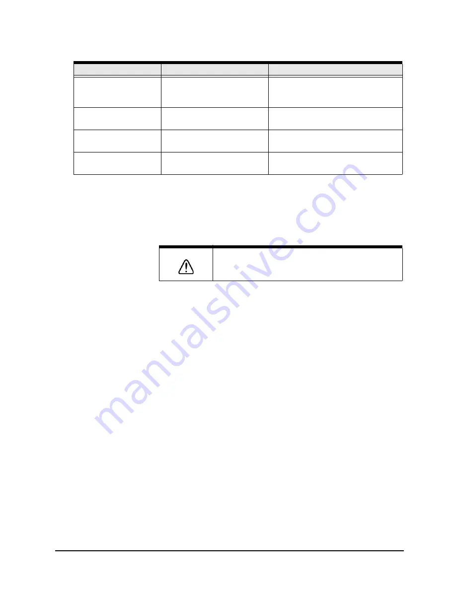
AUX
(6-pin connector)
RS-422/NMEA input/output
Northstar 491 echo sounder, or
older Northstar units for database
transfer
POWER (3-pin
connector)
Power input
10 to 36 VDC, 30 watts
VGA (15-pin D
connector)
Video output
Remote display
NTSC VIDEO INPUT
(BNC coaxial 75 Ohm)
Video input
Any NTSC-compatible video source
CAUTION!
To protect the power wiring, Northstar strongly recommends
that you connect the
6000i
to a circuit breaker or 7-amp fuse
located at the power source (battery or switch panel).
Table 6: Interface connector functions (continued)
Connector name
Connector function(s)
Connects to...
Summary of Contents for 6000i
Page 2: ......
Page 4: ......
Page 8: ...SECTION ONE Introducing the 6000i Page 4 6000i Installation Manual Rev G ...
Page 16: ...SECTION TWO Installing and wiring the 6000i Page 12 6000i Installation Manual Rev G ...
Page 30: ...SECTION FOUR Networking the Northstar 6000i Page 26 6000i Installation Manual Rev G ...
Page 34: ...SECTION FIVE Checking out the system Page 30 6000i Installation Manual Rev G ...
Page 48: ...SECTION SIX Interfacing the 6000i system Page 44 6000i Installation Manual Rev G ...
Page 56: ...APPENDIX A 6000i system technical specifications Page 52 6000i Installation Manual Rev G ...


