SECTION FOUR: Networking the Northstar 6000i
Page 22
6000i
Installation Manual, Rev. G
Cables in the table above are not stocked by the factory.
Cables in the table above are not stocked by the factory.
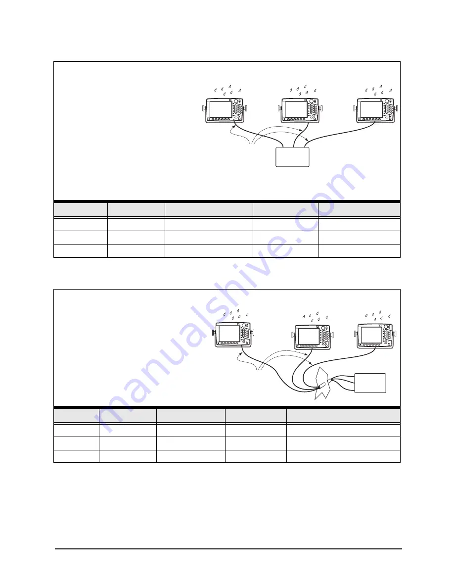
Straight cables,
one end waterproof
Standard
switch
(in dry location)
P/N
Length
Type
Cable end 1
Cable end 2
WA578-A
15 feet
Straight-through
Waterproof
Non-waterproof
WA579-A
30 feet
Straight-through
Waterproof
Non-waterproof
WA580-A
60 feet
Straight-through
Waterproof
Non-waterproof
Semi-waterproof straight-through cables
For applications where the Ethernet
switch is mounted in a dry area,
straight-through cables with
waterproof connectors on one end and
non-waterproof connectors on the
other are available from Northstar.
They are used to connect N2 devices
exposed to water to equipment
installed in a protected area. They have
a waterproof connector on one end and
an “open’” (non-waterproof) connector on the other end.
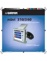
Straight-through cables,
semi-waterproof
one end unwired
for fishing through small space
Standard
switch
for dry
locations
P/N
Length
Type
Cable end 1
Cable end 2
WA578-B
15 feet (5 m)
Straight-through
Waterproof
Non-waterproof – Not installed
WA579-B
30 feet (10 m)
Straight-through
Waterproof
Non-waterproof – Not installed
WA580-B
60 feet (20 m)
Straight-through
Waterproof
Non-waterproof — Not installed
The following cables are identical to
those described above, except that
one connector is not installed, so
the cable can be fished through a
hole or tube. A kit containing the
second non-waterproof connector is
included for installation by the
technician (this requires special
tools — see page 25).
Semi-waterproof straight-through cables with one end unwired
Summary of Contents for 6000i
Page 2: ......
Page 4: ......
Page 8: ...SECTION ONE Introducing the 6000i Page 4 6000i Installation Manual Rev G ...
Page 16: ...SECTION TWO Installing and wiring the 6000i Page 12 6000i Installation Manual Rev G ...
Page 30: ...SECTION FOUR Networking the Northstar 6000i Page 26 6000i Installation Manual Rev G ...
Page 34: ...SECTION FIVE Checking out the system Page 30 6000i Installation Manual Rev G ...
Page 48: ...SECTION SIX Interfacing the 6000i system Page 44 6000i Installation Manual Rev G ...
Page 56: ...APPENDIX A 6000i system technical specifications Page 52 6000i Installation Manual Rev G ...


