6000i
Installation Manual, Rev. G
Page 5
SECTION TWO: Installing and
wiring the
6000i
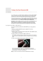
Bench-testing the
6000i
Northstar recommends bench-testing the
6000i
with a GPS antenna before installing it onto the
vessel. Bench testing ensures that the equipment is fully operational, and lets the unit collect the
current almanac and ephemeris data and a local position fix, which results in less on-board
installation time.
Mounting the
6000i
Choosing the best mounting location
Choose the mounting location carefully before you drill or cut. The 6000i should be installed in an
accessible, dry location where the operator can easily use the controls and clearly see the display
screen. Be sure to leave a direct path for all of the cables. The display screen is high-contrast and
anti-reflective, and is viewable in direct sunlight, but for best results, install the
6000i
out of direct
sunlight. The chosen location should have minimal glare from windows or bright objects. If the
6000i is yoke-mounted low, tilt the unit back for best viewing contrast.
WARNING!
Before starting the installation, be sure to turn electrical power
off. If power is left on or turned on during the installation, fire,
electrical shock, or other serious injury may occur.
Be sure that the voltage of the power supply is compatible with
the 6000i’s voltage rating of 10 to 36 volts DC. Connecting to the
wrong power supply can cause fire or damage to the equipment.
Be sure to ground the equipment to prevent electrical shock and
mutual interference.
Be sure to use a 7-amp fast-blow fuse in the supplied power
cable. Using the wrong fuse can cause fire or damage to the
6000i.
CAUTION!
Proper installation of the Northstar 6000i is critical to accurately receive
and effectively use GPS/WAAS signals under a wide variety of weather
conditions.
Keep the following safe compass distance from the 6000i: 1.0m
standard, 0.8m steering.
Summary of Contents for 6000i
Page 2: ......
Page 4: ......
Page 8: ...SECTION ONE Introducing the 6000i Page 4 6000i Installation Manual Rev G ...
Page 16: ...SECTION TWO Installing and wiring the 6000i Page 12 6000i Installation Manual Rev G ...
Page 30: ...SECTION FOUR Networking the Northstar 6000i Page 26 6000i Installation Manual Rev G ...
Page 34: ...SECTION FIVE Checking out the system Page 30 6000i Installation Manual Rev G ...
Page 48: ...SECTION SIX Interfacing the 6000i system Page 44 6000i Installation Manual Rev G ...
Page 56: ...APPENDIX A 6000i system technical specifications Page 52 6000i Installation Manual Rev G ...