background image


7


ASSEMBLE INSTRUCTIONS    


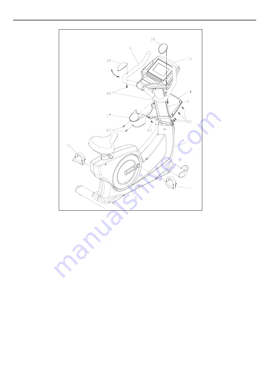
STEP 12 

Slide the 

Console Bracket (14)

 onto the 

Console (13) 

and secure with the 

Screw, Round 

Head (M5xp0.8x15mm)(83.) 


STEP 13 

a. Place the 

Hand Wrist Pad (28) 

onto the

 Handlebar (6.) 

b. Swing


the 

Hand Wrist Pad (28)

 to the most suitable position.   

c.  Secure it with the

 Bolt, Button Head (M6xp1.0x12mm)(88.)


STEP 14 

a. Remove the

 Screw, Round Head (M5xp0.8x15mm)(83) 

from the

 Upright Post(5)

b. Attach the 

Accessory Tray (17)

 onto the

 Upright Post (5)

 and secure with the

 Screw, Round Head 

(M5xp0.8x15mm)(83.) 


STEP 15 

Thread the 

Right Pedal (11)

 clockwise onto the

 Right Crank

 located inside the

 Right Crank Cover (9)


as shown. Tighten the pedal securely. Repeat the same procedure to thread and tighten the

 Left Pedal 

(10) 

counter-clockwise onto the 

Left Crank 

as shown. 

Summary of Contents for UG-7020

Page 1: ...of this equipment Serious bodily injury can occur if this equipment is not assembled and used correctly Serious bodily injury can also occur if all instructions are not followed Keep others and pets a...

Page 2: ...ithin them Always use common sense when exercising 12 Before using this product please consult your personal physician for a complete physical examination 13 Do not wear loose or dangling clothing whi...

Page 3: ...s a convenient and simple method to begin your assault on getting your body in shape and achieving a happier and healthier lifestyle Before reading further please review the drawing below and familiar...

Page 4: ...measured from below the head to the end of the bolt or screw Flat head bolts and screws are measured from the top of the head to the end of the bolt or screw After unpacking the unit open the hardwar...

Page 5: ...n Frame 1 and secure with the Washer 8x38x2 0t 73 the Lock Washer M8 78 and the Bolt Hex Head M8xp1 25x65mm 97 by using socket wrench as the main assembling drawing shows If the bike is not level revi...

Page 6: ...tration shown on the top right corner b Insert the Upright Post 5 into the Main Frame 1 and secure with the Bolt Hex Head M10xp1 5x50mm 99 by using the T HEAD SOCKET WRENCH 17MM as shown STEP 5 a Conn...

Page 7: ...ne is suitable for Nickel Metal Hybrid NI MH rechargeable batteries only c Install rechargeable batteries into the console STEP 8 Attach the Battery Door 16 onto the back of the Console 13 with the Sc...

Page 8: ...Bolt Button Head M6xp1 0x12mm 88 STEP 14 a Remove the Screw Round Head M5xp0 8x15mm 83 from the Upright Post 5 b Attach the Accessory Tray 17 onto the Upright Post 5 and secure with the Screw Round H...

Page 9: ...tment Bar 23 up to adjust the seat height Seat downward to lower the seat height or slight move the body upward to raise the seat height Once adjusting to the proper position release the Adjustment Ba...

Page 10: ...rew M3x10mm 79 at the bottom on the Console 13 by using the combination wrench to open the Battery Door 16 c Install and replace batteries The Console 13 operates with four AA rechargeable batteries f...

Page 11: ...P4 P6 P8 P10 P12 55 HRC 75 HRC 90 HRC T HR arget Manual User The console display may vary slightly from the actual console display the above console overview is for reference only The console has met...

Page 12: ...ound LCD diagram appears as below c Enter into the initial setting mode after around two seconds as below POWER OFF The console would automatically shut off after 30 seconds of inactivity NOTE the con...

Page 13: ...o MANUAL MODE immediately without selecting the function value displays of TIME DISTANCE CALORIES PULSE b START PAUSE button 1 Press to start a workout 2 Press to pause the program The console would d...

Page 14: ...o during setting b CHANGE SLECTED MODE MANUAL PROGRAM USER TARGET H R Under PAUSE MODE Hold the button for FOUR SECONDS to enter into the initial setting mode as shown RESET The RESET function only op...

Page 15: ...ght side c Enter into the initial setting mode after around two seconds as shown on right side 2 RESTART FUNCTION a Press the START PAUSE button to pause the current program b Hold the RESET button fo...

Page 16: ...for confirming and entering the function value setting d PAUSE MODE single will flash on LCD window for setting e LCD window then display flashing workload level as shown f UP or DOWN button Press th...

Page 17: ...Kcal Increment PULSE 70 to 240 BPM 1BPM increment Press the ENTER button to confirm the function value and enter the next function value setting Press the UP or DOWN button to select the value of the...

Page 18: ...ES 10 to 990 Kcal Yes During a workout The selected value will turn to zero after turning off Yes Use RESET button 1 Calories will count up to 990 Kcal and cycle run the program profile without settin...

Page 19: ...ght side c Enter into the initial setting mode after around two seconds as shown on right side 2 RESTART FUNCTION a Press the START PAUSE button to pause the current program c Hold the RESET button fo...

Page 20: ...the function value setting d PAUSE MODE single will appear on LCD window for setting e START PAUSE button After flashing P1 appears on LCD window press the START PAUSE button to start a workout direct...

Page 21: ...rs to set the function values TIME 01 00 to 99 00 1minute increment DISTANCE 0 1 to 99 9km 0 1km increment CALORIES 10 to 990 Kcal 10 Kcal Increment PULSE 70 to 240 BPM 1BPM increment Press the ENTER...

Page 22: ...geable resistance depends on the value of RPM Rotate Per Minute RPM RESISTANCE RPM RESISTANCE In order to remain the value of Watt Control the value of the RPM Rotate Per Minute increases when you ped...

Page 23: ...OGRAM MODE d ENTER button Press the ENTER button for confirming and entering the function value setting e UP or DOWN button Press the UP or DOWN button to choose P12 as the following illustration show...

Page 24: ...n to confirm the function value and enter the next function value setting To increase or decrease the value of the function TIME DISTANCE CALORIES PULSE press the UP or DOWN button To reset the functi...

Page 25: ...ght side c Enter into the initial setting mode after around two seconds as shown on right side 2 RESTART FUNCTION a Press the START PAUSE button to pause the current program b Hold the RESET button fo...

Page 26: ...setting d PAUSE MODE single will appear on LCD window for setting e START PAUSE button After flashing the first time interval of the workload level appears on LCD window press the START PAUSE button t...

Page 27: ...ugh the functions as follow and allow users to set the function values TIME 01 00 to 99 00 1minute increment DISTANCE 0 1 to 99 9km 0 1km increment CALORIES 10 to 990 Kcal 10 Kcal Increment PULSE 70 t...

Page 28: ...right side c Enter into the initial setting mode after around two seconds as shown on right side 2 RESTART FUNCTION a Press the START PAUSE button to pause the current program b Hold the RESET button...

Page 29: ...console preset appear on the LCD window press the UP or DOWN button to select your age f ENTER button Press the ENTER button to confirm the user s age g UP or DOWN button Continue to select the TARGET...

Page 30: ...e function values TIME 01 00 to 99 00 1minute increment DISTANCE 0 1 to 99 9km 0 1km increment CALORIES 10 to 990 Kcal 10 Kcal Increment PULSE 70 to 240 BPM 1BPM increment Press the ENTER button to co...

Page 31: ...e legs as wide as possible Stretch the upper body toward the knee on the right leg by using your arms to pull your chest to your thighs Hold this stretch 10 to 30 seconds DO NOT BOUNCE Do this stretch...

Page 32: ...sing 2 32 Pulse Sensor Bottom Housing 2 33 Pulse Sensor Plate 4 34 Generator 1 35 Pulley 120mm 1 NO PARTS NAME Q TY 36 Belt 762mm J8 1 37 Pulley 235mm 1 38 Magnet 1 39 Belt 1092mm J8 1 40 Front Alumin...

Page 33: ...ead M8 p1 25 16mm 5 91 Bolt Button Head M10 p1 5 45mm 1 92 Screw Flat Head M8 p1 25 12mm 5 93 Bolt Socket Head M8 p1 25 70mm 2 94 Bolt Socket Head M10 p1 5 30mm 1 NO PARTS NAME Q TY 95 Bolt Hex Head M...

Page 34: ...33 PRODUCT PARTS DRAWING...

Reviews: