38
EN
External signal specifications
I/O circuit
CAUTION
z
z
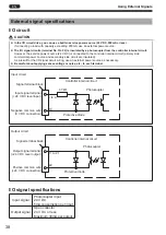
In the I/O circuit drive, you can use a built-in service power source (24 V DC, 200mA or less).
If connecting a load with capacity exceeding 200mA, use an external power source.
z
z
The I/O signal circuits (terminal No.3 to 22) is insulated by a photocoupler from the controller internal circuit.
However, the service power source (24 V DC) is connected to the controller internal circuit (primary side
commercial power source and secondary side circuit are insulated).
As a result for the I/O signal circuit wiring, use an external power source as necessary.
z
z
Be careful about applying excess voltage or noise, etc., to each terminal.
Input circuit
Input signal terminal
(+24 V DC level input)
Negative common wire
(0 V DC connection)
Signal terminal block
Controller internal circuit
4.7kΩ
Protective diode
Photocoupler
10
3 to 9
Output circuit
Output signal terminal
(+24 V DC level output)
Positive common wire
(+24 V DC connection)
Signal terminal block
Controller internal circuit
Protective diode
Photocoupler
22
11 to 21
I/O signal specifications
Input signal
Photocoupler input
24 V DC
5mA consumption per input
Output signal
Open collector
24 V DC or less
Maximum 30mA per output
Using External Signals
TV07783-1_DLV10C_en.indb 38
2017/06/27 17:41:40

