56 - FORM NO. 56043051 / Retriever
™
2060
HYDRAULIC SYSTEM
Z
Y
V
X
W
T
FRONT
U
R
L
________________________________________________________________________________________________________________________________________________________________________________________________________________________________________________________________________
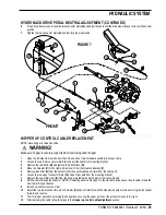
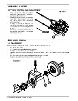
HOPPER UP CONTROL CABLE ADJUSTMENT
________________________________________________________________________________________________________________________________________________________________________________________________________________________________________________________________________
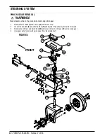
STEER WHEEL REMOVAL
WARNING!
Never work under a machine without safety blocks or stands to support the machine.
1
Turn steering wheel to left.
2
Turn off engine, set parking brake and block front wheels.
3
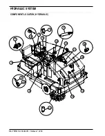
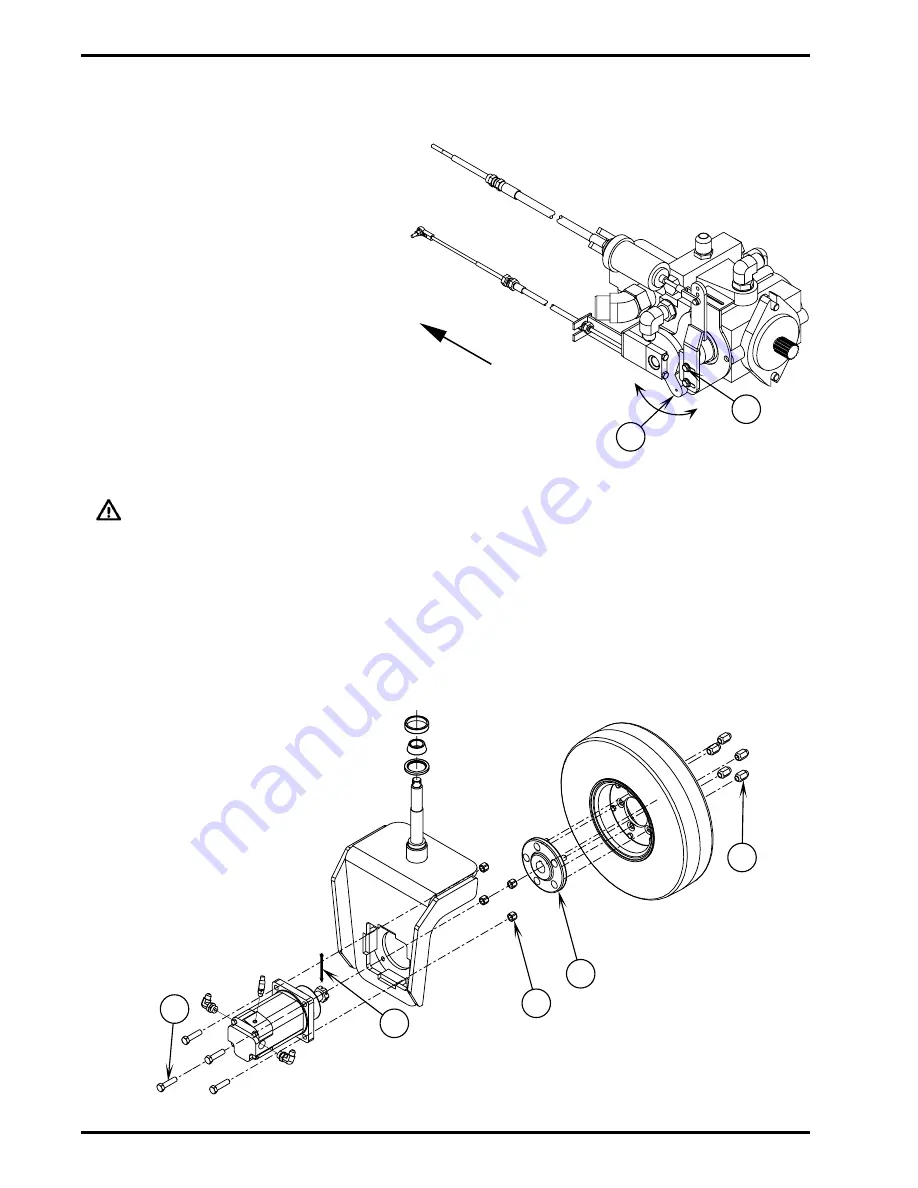
See Figure 9. Loosen the five wheel Lug Nuts (V).
4
If removing drive motor, remove Cotter Pin (W) and loosen center castle nut. NOTE: You will need a 1-7/16 inch socket for castle
nut.
5
Jack up machine until wheel clears ground and place jack stands under machine.
6
Remove Lug Nuts (V) and pull the wheel off the Hub Assembly (X).
1
Observe the top speed of the machine with the
hopper in the lowered position. It should be ap-
proximately 9 MPH (14 kms/hour).
2
Raise the hopper and determine the top speed of
the machine, it should be about 25% of the top
speed with the hopper lowered or between 2-3
MPH (3-5 kms/hour).
3
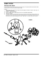
See Figure 8. Loosen the two Bolts (T) and slide
the Cam Plate (U) to the right to increase the speed
or to the left to decrease the speed. Tighten the two
Bolts (T).
4
Repeat steps 1-3 until the speed of the machine
with the hopper raised is about 25% of the speed
with the hopper lowered.
FIGURE 8
FIGURE 9
Summary of Contents for Advance Retriever 2060
Page 87: ...4 99 Form No 56040696 page 2 A 3 B C D 5 1 2 6...
Page 94: ...6 99 revised 3 00 Form No 56040702 page 2 5 3 2 6 6 5 3 4 1 2...
Page 111: ...9 00 Form No 56040733 page 2 of 3 Diesel H FRONT M K L N R W P O T S J Q O P U V FIGURE 1...
Page 128: ...PROGRAM PURPOSE and OBJECT ZENITH FUEL SYSTEMS Page 1 1 5 48 7 0 1 2 3 4 5 0 50...
Page 133: ...ZENITH FUEL SYSTEMS Page 5 1 5 0 50 A 50 4 4 B 8 6 A C D FIG 5 1...
Page 134: ...ZENITH FUEL SYSTEMS Page 5 2 6 5 8 0 8 2 0 2 0 2 E F 0 D 50 4 C D 5 5 5 5 6 6 2 0 6 FIG 5 2...
Page 139: ...Fuel Enrichment 4 6 6 50 5 5 6 A 50 5 0 0 ZENITH FUEL SYSTEMS Page 5 7...
Page 144: ...ZENITH FUEL SYSTEMS INC Page 5 12 3F 6 6 H J 3F FIG 5 19 6 G 6 FIG 5 20...
Page 147: ...ZENITH FUEL SYSTEMS Page 6 2 A A 1 6 FIG 6 1...
Page 148: ...ZENITH FUEL SYSTEMS Page 6 3 5 2 3 0 0 1 4 4 B 6 6 6 4 4 3 6 6 6 9 6 6...
Page 149: ...ZENITH FUEL SYSTEMS Page 7 2 8 2...
Page 150: ...ZENITH FUEL SYSTEMS Page 7 3 8 2...
Page 153: ...ZENITH FUEL SYSTEMS Page 9 3...
Page 160: ...ZENITH FUEL SYSTEMS Page 9 11 6 6 9 8 2...
Page 163: ...ZENITH FUEL SYSTEMS Page 9 14 6 6 9 8 Continued...

