
Form No. 56040718
(page 5 of 7)
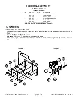
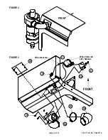
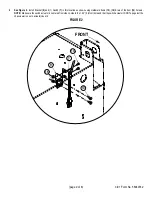
1.06
“
1.43
“
C
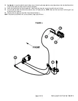
FRONT
J
F
ø .
15
“
(3.8 mm)
ø .
15
“
(3.8 mm)
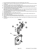
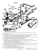
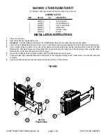
FIGURE 5
32
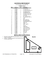
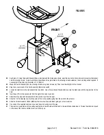
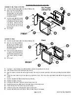
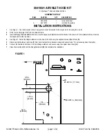
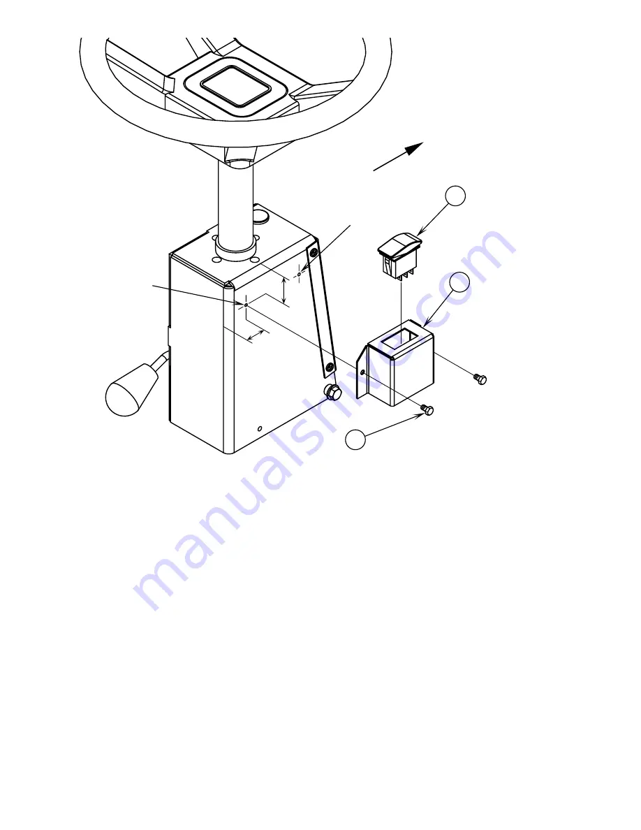
See Figure 5. Using the Switch Bracket (C) as a template and the dimensions shown, mark the location for the two holes for mounting the bracket
onto the steering column. Some machines will have these holes pre-drilled on the steering column weldment, then no drilling will be required. If
necessary drill two holes to a diameter of .15” (3.8mm).
33
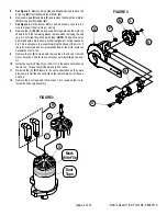
Mount the Switch Bracket (C) to the steering column using (two) Screws (J). Then insert Switch (F) into the bracket.
34
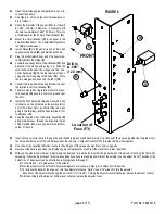
Plug the connector end of the Cord Assembly (Q) into the switch.
35
Locate the small hole in the cab beneath the fuse block. Use a Screw (J) and Washer (K) to secure the black wire with the ring terminal to this
hole.
36
Insert Fuse (Y) into the second slot from the right of the cab’s fuse block.
37
Attach the blue wire with the receptacle to the second fuse from the right.
38
Slide the 1/2” Conduit (L) over the three wires of the cord assembly going from the switch to the actuator.
39
Slide the smaller diameter Conduit (M) over the two wires (blue and black) going up to the fuse block.
40
Use some of the supplied cable ties to secure the switch wiring out of the way.
41
The side broom actuator switch is used by pushing the rocker forward until the broom is lowered the desired amount. To raise the side broom push
on the back of the rocker until the broom is all the way up.
Revised 11/00
Summary of Contents for Advance Retriever 2060
Page 87: ...4 99 Form No 56040696 page 2 A 3 B C D 5 1 2 6...
Page 94: ...6 99 revised 3 00 Form No 56040702 page 2 5 3 2 6 6 5 3 4 1 2...
Page 111: ...9 00 Form No 56040733 page 2 of 3 Diesel H FRONT M K L N R W P O T S J Q O P U V FIGURE 1...
Page 128: ...PROGRAM PURPOSE and OBJECT ZENITH FUEL SYSTEMS Page 1 1 5 48 7 0 1 2 3 4 5 0 50...
Page 133: ...ZENITH FUEL SYSTEMS Page 5 1 5 0 50 A 50 4 4 B 8 6 A C D FIG 5 1...
Page 134: ...ZENITH FUEL SYSTEMS Page 5 2 6 5 8 0 8 2 0 2 0 2 E F 0 D 50 4 C D 5 5 5 5 6 6 2 0 6 FIG 5 2...
Page 139: ...Fuel Enrichment 4 6 6 50 5 5 6 A 50 5 0 0 ZENITH FUEL SYSTEMS Page 5 7...
Page 144: ...ZENITH FUEL SYSTEMS INC Page 5 12 3F 6 6 H J 3F FIG 5 19 6 G 6 FIG 5 20...
Page 147: ...ZENITH FUEL SYSTEMS Page 6 2 A A 1 6 FIG 6 1...
Page 148: ...ZENITH FUEL SYSTEMS Page 6 3 5 2 3 0 0 1 4 4 B 6 6 6 4 4 3 6 6 6 9 6 6...
Page 149: ...ZENITH FUEL SYSTEMS Page 7 2 8 2...
Page 150: ...ZENITH FUEL SYSTEMS Page 7 3 8 2...
Page 153: ...ZENITH FUEL SYSTEMS Page 9 3...
Page 160: ...ZENITH FUEL SYSTEMS Page 9 11 6 6 9 8 2...
Page 163: ...ZENITH FUEL SYSTEMS Page 9 14 6 6 9 8 Continued...


