4/99 revised 8/01 Form No. 56040693
(page 5 of 6)
FRONT
F
P
Kubota Parts
Chase thread with
1/8-27 NPT tap
E
AA
BB
G
FRONT
Q
Z
FIGURE 6
FIGURE 6
FIGURE 6
FIGURE 6
FIGURE 6
FIGURE 7
FIGURE 7
FIGURE 7
FIGURE 7
FIGURE 7
Diesel
Diesel
Diesel
Diesel
Diesel
Coolant Temperature
•••••
Drain a portion of the coolant from the radiator to prevent
losing the fluid when the pipe plug is removed from the en-
gine block.
•••••
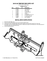
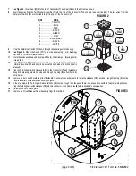
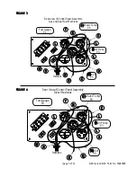
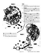
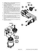
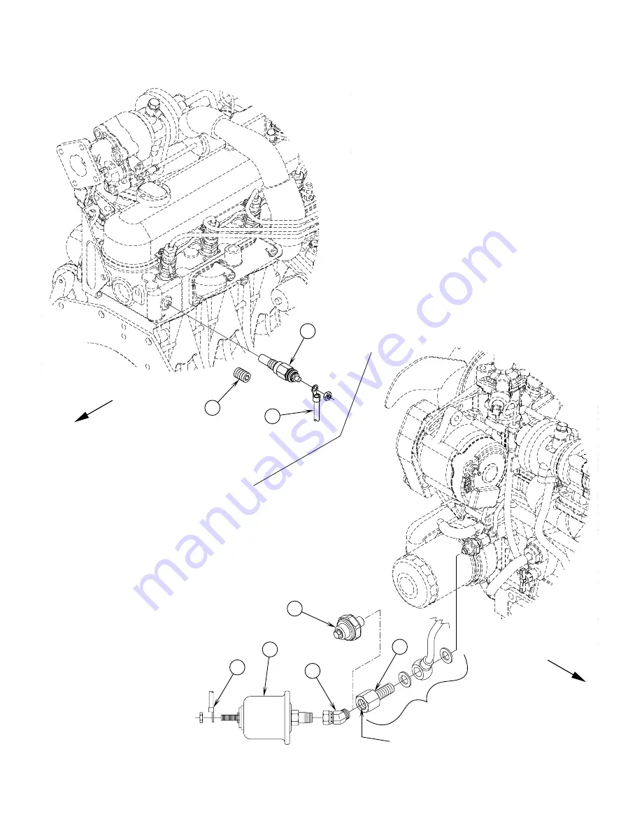
See Figure 6.
See Figure 6.
See Figure 6.
See Figure 6.
See Figure 6. Locate and remove Pipe Plug (Z)
(Z)
(Z)
(Z)
(Z) from engine
block and install Temperature Sender (G)
(G)
(G)
(G)
(G). Use pipe sealant.
Plug is located on intake side of the engine block near the
back and top. Hook up wire (Q)
(Q)
(Q)
(Q)
(Q) to the temperature sender
and re-fill the radiator.
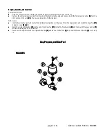
Oil Pressure
•••••
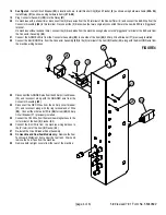
See Figure 7.
See Figure 7.
See Figure 7.
See Figure 7.
See Figure 7. Locate and remove the Oil Sender (AA)
(AA)
(AA)
(AA)
(AA). Re-
move the Kubota Fitting (BB)
(BB)
(BB)
(BB)
(BB) from the engine block and use
a 1/8-27 NPT pipe tap to clear the threads to accept the el-
bow (P)
(P)
(P)
(P)
(P). Thoroughly clean and reinstall the Kubota part, in-
sure that seal washers are in place.
•••••
Install Elbow (P)
(P)
(P)
(P)
(P) into modified Kubota Fitting (BB)
(BB)
(BB)
(BB)
(BB) point the
elbow away from the alternator so that the Oil Pressure
Sender (F)
(F)
(F)
(F)
(F) can be installed without interference. Then in-
stall oil pressure sender into Elbow (P)
(P)
(P)
(P)
(P).
•••••
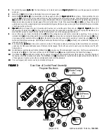
Connect the White Wire (E)
(E)
(E)
(E)
(E) to the new Oil Pressure Sender
(F)
(F)
(F)
(F)
(F). Tape the ring terminal on the GRA/BLK wire that was
removed from the old oil pressure sender. Secure the wire
to the wiring harness. Go to step 14.
14
14
14
14
14
Use the Cable Ties (O)
(O)
(O)
(O)
(O) to secure the wires.
15
15
15
15
15
Check to be sure coolant is at the proper
level.
16
16
16
16
16
Reconnect the battery, start the machine and
check the new gauges for proper operation.
Summary of Contents for Advance Retriever 2060
Page 87: ...4 99 Form No 56040696 page 2 A 3 B C D 5 1 2 6...
Page 94: ...6 99 revised 3 00 Form No 56040702 page 2 5 3 2 6 6 5 3 4 1 2...
Page 111: ...9 00 Form No 56040733 page 2 of 3 Diesel H FRONT M K L N R W P O T S J Q O P U V FIGURE 1...
Page 128: ...PROGRAM PURPOSE and OBJECT ZENITH FUEL SYSTEMS Page 1 1 5 48 7 0 1 2 3 4 5 0 50...
Page 133: ...ZENITH FUEL SYSTEMS Page 5 1 5 0 50 A 50 4 4 B 8 6 A C D FIG 5 1...
Page 134: ...ZENITH FUEL SYSTEMS Page 5 2 6 5 8 0 8 2 0 2 0 2 E F 0 D 50 4 C D 5 5 5 5 6 6 2 0 6 FIG 5 2...
Page 139: ...Fuel Enrichment 4 6 6 50 5 5 6 A 50 5 0 0 ZENITH FUEL SYSTEMS Page 5 7...
Page 144: ...ZENITH FUEL SYSTEMS INC Page 5 12 3F 6 6 H J 3F FIG 5 19 6 G 6 FIG 5 20...
Page 147: ...ZENITH FUEL SYSTEMS Page 6 2 A A 1 6 FIG 6 1...
Page 148: ...ZENITH FUEL SYSTEMS Page 6 3 5 2 3 0 0 1 4 4 B 6 6 6 4 4 3 6 6 6 9 6 6...
Page 149: ...ZENITH FUEL SYSTEMS Page 7 2 8 2...
Page 150: ...ZENITH FUEL SYSTEMS Page 7 3 8 2...
Page 153: ...ZENITH FUEL SYSTEMS Page 9 3...
Page 160: ...ZENITH FUEL SYSTEMS Page 9 11 6 6 9 8 2...
Page 163: ...ZENITH FUEL SYSTEMS Page 9 14 6 6 9 8 Continued...

