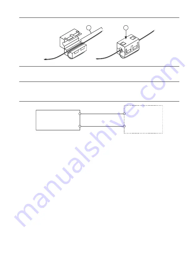
Figure 3. Installing a Ferrite on the Power Leads
1
2
1. Pass the leads through the ferrite twice, leaving 50 mm to 75 mm (2 in. to 3 in.) between the ferrite and
the end of the leads.
2. Close the ferrite around the leads.
3.
Remove the power connector from the cRIO-905
x
.
4.
Connect the power supply to the power connector, as shown in the following figure.
Figure 4. cRIO-905x Power Connections
Power Connector
C
V
Power Supply
+
–
5.
Tighten the terminal screws on the power connector to 0.20 N · m to 0.25 N · m
(1.8 lb · in to 2.2 lb · in) of torque.
6.
Install the power connector on the front panel of the cRIO-905
x
.
7.
Tighten the power connector screw flanges to 0.20 N · m to 0.25 N · m
(1.8 lb · in to 2.2 lb · in) of torque.
8.
Power on the primary power supply.
When you power on the cRIO-905
x
for the first time, the device boots into safe mode.
The POWER LED illuminates, the STATUS LED illuminates briefly, and then the
STATUS LED blinks twice every few seconds, indicating the controller does not yet have
software installed.
Connecting the Controller to the Host Computer
Complete the following steps to connect the cRIO-905
x
to the host computer using the USB
Type-C Device Port with Console Out.
1.
Power on the host computer.
2.
Connect the cRIO-905
x
to the host computer using the USB-Type-C-to-USB-Type-A
cable (included in kit), inserting the USB Type-C connector into the USB Type-C Device
Port with Console Out. Connect the other end of the USB cable (Type-A) to the host
computer.
The device driver software automatically detects the cRIO-905
x
. Select
Configure and
install software to this device
.
8
|
ni.com
|
cRIO-905x Getting Started Guide


