background image

GETTING STARTED GUIDE

cRIO-905x

Embedded CompactRIO Controller with Real-Time Processor and
Reconfigurable FPGA

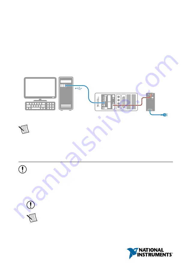
This document describes how to begin using the cRIO-905

x

.

In this document, the cRIO-9053, cRIO-9054, cRIO-9055, cRIO-9056, cRIO-9057, and
cRIO-9058 are referred to collectively as cRIO-905

x

.

Note


Refer to the device Safety, Environmental, and Regulatory Information

document, shipped with your cRIO-905

x

 controller and available on 

ni.com/

manuals

, for important safety and environmental specifications necessary when

setting up your device.

Unpacking the Kit

Notice


To prevent electrostatic discharge (ESD) from damaging the device, ground

yourself using a grounding strap or by holding a grounded object, such as your
computer chassis.

1.

Touch the antistatic package to a metal part of the computer chassis.

2.

Remove the device from the package and inspect the device for loose components or any
other sign of damage.

Notice


Never touch the exposed pins of connectors.

Note


Do not install a device if it appears damaged in any way.

3.

Unpack any other items and documentation from the kit.

Summary of Contents for cRIO-905 Series

Page 1: ...manuals for important safety and environmental specifications necessary when setting up your device Unpacking the Kit Notice To prevent electrostatic discharge ESD from damaging the device ground you...

Page 2: ...Supply Installing Software on the Host Computer If you do not currently have any NI software installed on your host computer see the Install Software section for details on required software and in w...

Page 3: ...patibility issues with CompactRIO systems visit ni com info and enter the Info Code swcompatibility Note If you try to install software that already exists on your host computer the installer will sho...

Page 4: ...a nonhazardous location the cRIO 905x can be powered on when you install modules 2 Press the latches on the C Series module 3 Align the C Series module with a slot and seat it in the slot until the la...

Page 5: ...port or 2 Ethernet ports depending on the model Connecting the Controller to Ground You must connect the cRIO 905x grounding terminal to the grounding electrode system of the facility What to Use Rin...

Page 6: ...rounding terminal using 1 3 mm2 16 AWG or larger wire Attach a ring lug to the wire and attach the wire to the chassis grounding terminal Solder the other end of the wire to the cable shield Use short...

Page 7: ...r 2 54 mm 0 10 in flathead Power supply 9 V to 30 V 60 W minimum NI recommends the power supplies listed in the following table for the cRIO 905x Table 2 NI Power Supplies Power Supply Part Number NI...

Page 8: ...on the primary power supply When you power on the cRIO 905x for the first time the device boots into safe mode The POWER LED illuminates the STATUS LED illuminates briefly and then the STATUS LED blin...

Page 9: ...ter Discovering the Controller in MAX Complete the following steps to find the cRIO 905x controller in MAX 1 Launch MAX on the host computer 2 Expand Remote Systems in the configuration tree and locat...

Page 10: ...k the Set Permissions button in the toolbar The NI Web Based Configuration and Monitoring utility opens in your default browser and is where you set the password If you have not installed Microsoft Si...

Page 11: ...Software Wizard Tip You must log in to install software on the cRIO 905x The default username for the cRIO 905x is admin There is no default password for the cRIO 905x To set a password for your syst...

Page 12: ...AQmx programming mode For additional information refer to Installing Software on the Host Computer and Choosing Your Programming Mode in the cRIO 905x User Manual 1 Launch MAX 2 Locate and select your...

Page 13: ...t Panels or select Test Panels from the main configuration window options Note If the module you select is not deployed in Real Time NI DAQmx mode you will be prompted to switch modes to view the test...

Page 14: ...e in MAX 1 Launch MAX on the host computer 2 Expand Remote Systems in the configuration tree and locate your cRIO 905x system 3 Select the C Series module you wish to program 4 In the Settings pane ch...

Page 15: ...e is deployed in the program mode Notice the module icon changes to represent the program mode 1 Real Time Mode 2 Real Time Scan IO Variables Mode 3 LabVIEW FPGA Mode cRIO 905x Getting Started Guide N...

Page 16: ...al Use the RJ 45 Ethernet port 0 or port 1 to reconnect the cRIO 905x to the host computer The cRIO 905x attempts to initiate a DHCP network connection at power up Note If the cRIO 905x cannot obtain...

Page 17: ...he IP and other network settings 6 Reboot the cRIO 905x by pressing the RESET button Configure the Windows Firewall Use this topic to configure the firewall in Windows to ensure you cRIO 905x can comm...

Page 18: ...software has been improperly installed on the cRIO 905x An error can occur when an attempt to upgrade the software is interrupted Reinstall software on the cRIO 905x Refer to Installing Software on th...

Page 19: ...EW Project 2 Deploying Your C Series Module in a Programming Mode in LabVIEW Using the cRIO 905x in LabVIEW FPGA Requires LabVIEW FPGA Module Programming Modes Real Time Real Time Scan IO Variables La...

Page 20: ...click Finish 3 To add your system to the project right click the top of the project tree and select New Targets and Devices to launch the Add Targets and Devices discovery dialog 4 In the Add Targets...

Page 21: ...perly configured with a valid IP address in Measurement Automation Explorer If your system is on a remote subnet you can also select to manually enter the IP address You can locate the system IP addre...

Page 22: ...in a new programming mode in the LabVIEW project 1 Locate your C Series module in your LabVIEW project If you just created the project all C Series modules appear under Real Time Resources which indi...

Page 23: ...rogram the user accessible FPGA on the cRIO 905x or deploy C Series modules in the LabVIEW FPGA program mode To program in Real Time NI DAQmx or Real Time Scan IO Variables modes the LabVIEW FPGA modu...

Page 24: ...ick Next Note You can locate the system IP address in MAX in the System Settings for the cRIO 905x 6 In the LabVIEW Project Explorer verify that your system is present in the project tree and click Fi...

Page 25: ...that they are in the LabVIEW FPGA programming mode 2 Drag your C Series module to Real Time Scan Resources This indicates you plan to use your module in Real Time Scan IO Variables programming mode 3...

Page 26: ...port you have access to everything from troubleshooting and application development self help resources to email and phone assistance from NI Application Engineers Visit ni com services for informatio...

Page 27: ...ts EULAs and third party legal notices in the readme file for your NI product Refer to the Export Compliance Information at ni com legal export compliance for the NI global trade compliance policy and...

Reviews: