MASTERTRACE
Chapter 7 Networking Modules
7.3
available from the factory upon request. Programming the
Modbus registers and software to extract data from the
registers should be done by someone familiar with the
third party equipment.
7.6 Baud Rate
The communication baud rate determines how fast data is
sent along the data highway. Baud rates available are 600,
1200, 2400, 4800 and 9600 bits per second. The default
baud rate is 1200. Each device on the network must be set
at the same baud rate in order to communicate. The user
may increase the baud rate but noise immunity, with long
cable lengths, is reduced. When changing baud rate
through an MR100 or MR100 for Windows CE Group
Intreface, change the baud rate of each control module
connected to the data highway first and the Group
Intreface last. Be sure to select the correct serial port on
the control module.
7.7 Ethernet Communication in Modbus TCP and
MasterTrace Heat Tracing Panel Option “ETH”
In
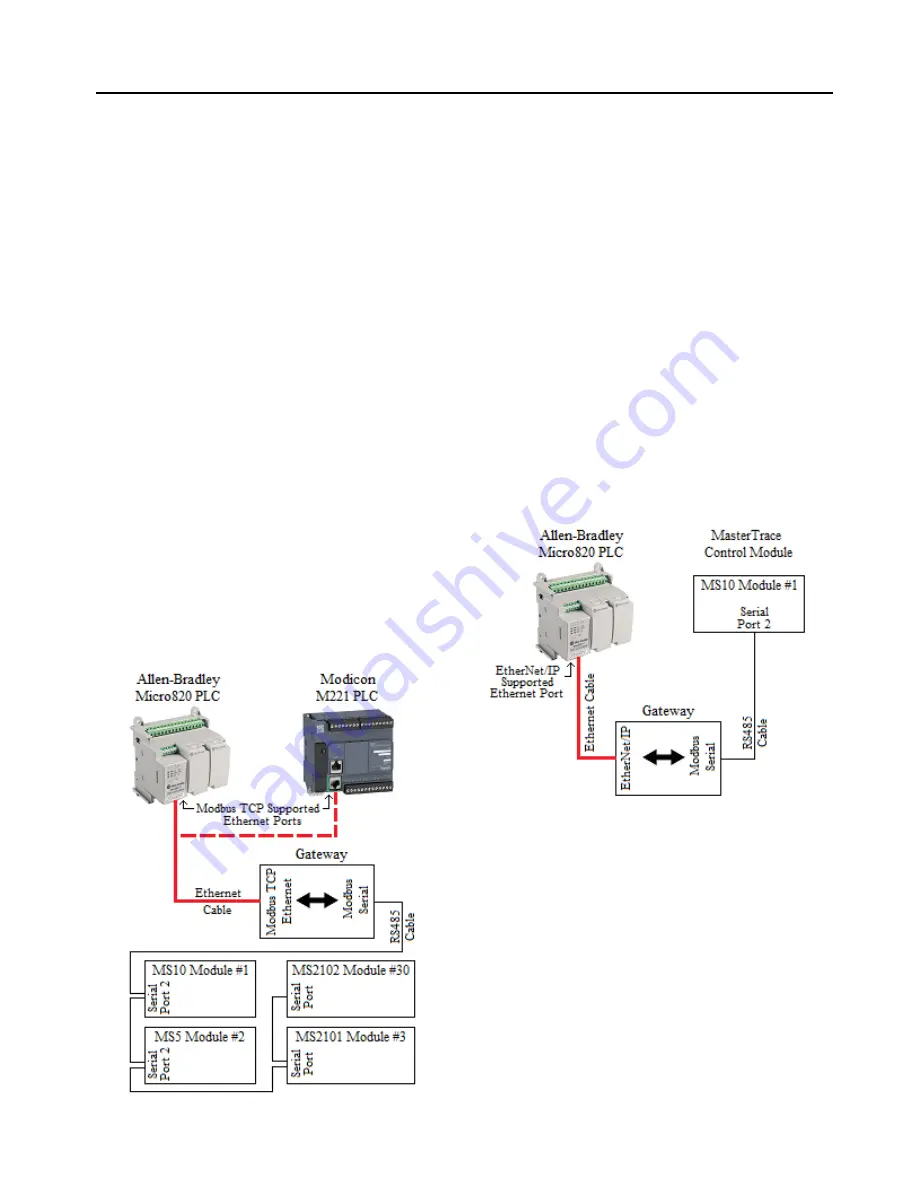
Figure 7.2
, Ethernet communication in Modbus TCP is
added to MasterTrace heat tracing panel by Modbus TCP
Ethernet to Modbus Serial gateway. The gateway (ex.
GC-NET485-MB from Grid Connect) is a Modbus RS485
serial to Modbus TCP Ethernet converter. The RS485 side
can connect to the serial port 2 of MasterTrace control
modules over long distances (up to 4000 feet). The
Figure 7.2 Modbus TCP Ethernet Communication
Ethernet side converts the serial Modbus data stream to
Modbus TCP Ethernet packets.
Connect a PLC or Automation system to the gateway
through its Ethernet port and use it as the Master in the
network. You can program the Master according to
MasterTrace Modbus Communication Protocol to
write/read data to/from MasterTrace control modules over
Ethernet from anywhere in the plant as long as the
Ethernet port on the PLC or Automation system is
Modbus TCP supported and is assigned to an IP address
that is different to the IP addresses of the gateway and
other devices in the Ethernet network. Most of PLCs and
Automation systems such as Micro820 from
Allen-Bradley and M221 from Modicon do have this kind
of Ethernet port as built-in.
ETH
, an additional option, has been added to the
MasterTrace heat tracing panel model codes to allow
customers to purchase Nextron panels with Ethernet
communication capability. Refer to
Chapter 3.4
for
Model
Codes for Control Panels
.
Figure 7.3 EtherNet/IP Communication
7.8 Ethernet Communication in EtherNet/IP
In
Figure 7.3
, Ethernet communication in EtherNet/IP is
added to MasterTrace heat tracing control module by
EtherNet/IP to Modbus Serial gateway. The gateway (ex.
GC-NET485-EIP-MB from Grid Connect) has 2 sides.
The Modbus Serial side connects to a single MasterTrace
control module through RS485 cable and acts as a master
in the Modbus RTU communication network. The
EtherNet/IP side connects to a PLC’s EtherNet/IP
supported Ethernet port via Ethernet cable and functions
as a server in the EtherNet/IP communication network.
With Modbus master and EtherNet/IP slave software
built-in, the gateway regularly polls Modbus registers’
data from the MasterTrace control module once it is
configured by any EtherNet/IP configuration tool. The
polled Modbus data is then translated into EtherNet/IP
assembly data which can be read in standard EtherNet/IP
Summary of Contents for MASTERTRACE
Page 1: ...MASTERTRACE TM OPERATOR S MANUAL HEAT TRACING CONTROL ...
Page 54: ...MASTERTRACE Chapter 7 Networking Modules 7 2 Figure 7 1 MASTERTRACE System Network ...
Page 87: ...D 2 MASTERTRACE Appendix D Typical Wiring Diagrams MS 2DXH0 MS 2DIN2 MS 5ADXH0 ...
Page 88: ...MASTERTRACE D 3 Appendix D Typical Wiring Diagrams MS 5ADIN2 MS 5ATXH0 ...
Page 89: ...D 4 MASTERTRACE Appendix D Typical Wiring Diagrams MS 10ADIN2 MS 10ADXH0 ...
Page 90: ...MASTERTRACE D 5 Appendix D Typical Wiring Diagrams MS 10ADIN2X MS 10ADIN2T ...
Page 91: ...D 6 MASTERTRACE Appendix D Typical Wiring Diagrams Driving Contactors Serial Communication 1 ...
Page 92: ...MASTERTRACE D 7 Appendix D Typical Wiring Diagrams Serial Communication 2 ...


