MASTER
TRACE
3.1
Chapter 3 Product Description
3 Product Description
3.1 Introduction
Electric heat tracing control schemes have generally used
some combination of mechanical thermostats, custom built
control panels or programmable controls to provide the re-
quired level of control, monitoring and alarm functions.
Budgetary constraints usually limit the degree of system
fault monitoring to less than optimal levels. This results in
periodic costly process shutdowns due to process or hard-
ware malfunctions. Equipment reliability concerns often
force plant procedures to include annual thermostat per-
formance checks to ensure that the device is still operating
as intended. This can be a tedious, labour intensive job.
The MasterTrace™ heat tracing system is a compatible fam-
ily of electronic controls that uses state of the art technol-
ogy to give complete control and central monitoring of elec-
tric heat tracing systems. MasterTrace™ can be used with
MI, self-regulating and constant wattage cable. Individual
smart controls mounted near to the pipe being traced can
communicate with a single master unit to give complete sys-
tem monitoring and control from a convenient location.
Continuous process and hardware monitoring with alarms
for the complete system at a central point eliminates the
need for annual maintenance checks. Overall system cost is
lower than custom panels that have far less capability due
to the many standard features incorporated into each con-
trol.
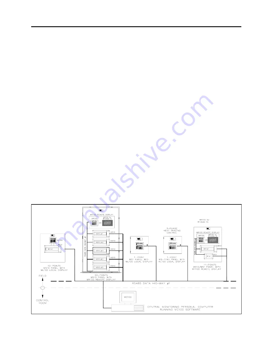
Each heater point is monitored by a control mounted near
the pipe being traced. Up to 300 points can be monitored by
a single master conveniently located to allow quick system
monitoring and fault diagnosis. A second RS485 port can be
used for communication between controls and centralized
monitoring. Each local control is completely independent
and will continue to function if the master fails or if the
communication link fails. This ensures maximum reliability
and minimizes vulnerability in the event of a hardware fail-
ure. Additional points can be added at any time as easily as
a mechanical thermostat can be installed. Unlike control
schemes using programmable controllers, no software de-
velopment is required. The complete system is operational
as soon as it is installed.
To ensure that the MasterTrace™ heat tracing system will
continue to meet the needs of plants as they upgrade to
fully automated operation, an additional data highway can
be implemented using the second RS485 port. By connect-
ing controls to a programmable controller that is tied into a
central plant computer, alarms caused by heat tracing mal-
functions can immediately be flagged in a central control
location. The complete system can be monitored and prob-
lem descriptions can be received for fast fault diagnosis
and repair. In addition, the setpoints of any remote control
can be altered by the master control (MR100 or MR100 for
Windows CE) or a central computer (MC100). Heaters can
be manually forced on and any pipe temperature can be
read.
Figure 3.1 MasterTrace™ System Concept
Summary of Contents for MASTERTRACE
Page 1: ...MASTERTRACE TM OPERATOR S MANUAL HEAT TRACING CONTROL ...
Page 54: ...MASTERTRACE Chapter 7 Networking Modules 7 2 Figure 7 1 MASTERTRACE System Network ...
Page 87: ...D 2 MASTERTRACE Appendix D Typical Wiring Diagrams MS 2DXH0 MS 2DIN2 MS 5ADXH0 ...
Page 88: ...MASTERTRACE D 3 Appendix D Typical Wiring Diagrams MS 5ADIN2 MS 5ATXH0 ...
Page 89: ...D 4 MASTERTRACE Appendix D Typical Wiring Diagrams MS 10ADIN2 MS 10ADXH0 ...
Page 90: ...MASTERTRACE D 5 Appendix D Typical Wiring Diagrams MS 10ADIN2X MS 10ADIN2T ...
Page 91: ...D 6 MASTERTRACE Appendix D Typical Wiring Diagrams Driving Contactors Serial Communication 1 ...
Page 92: ...MASTERTRACE D 7 Appendix D Typical Wiring Diagrams Serial Communication 2 ...


