background image

NTI Secure Remote Power Reboot Switch 


41


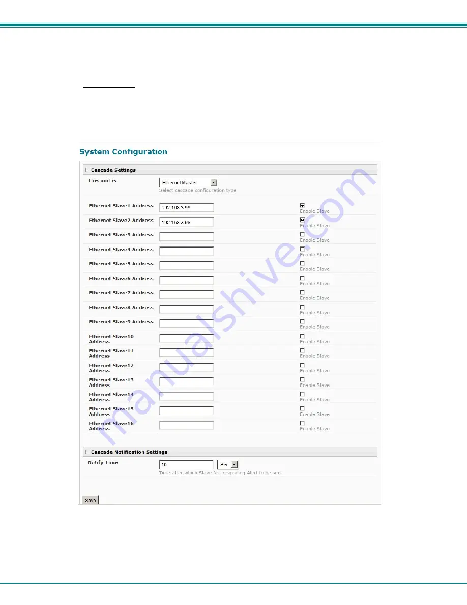
Ethernet Master 

If the type is 

Ethernet Master

, then the Slave IP Address Settings


must be entered for each slave that will be controlled.    The IP 

address will be used by the master to locate and communicate with the slave.  Once an IP address has been entered, and the 
Ethernet slave has been properly configured to be cascaded as part of this system, place a checkmark in the “Enable Slave” 
block.     


Figure 44

- Configure as Ethernet Master 


Summary of Contents for ENVIROMUX IPDU-Sx

Page 1: ...MAN119 Rev Date 4 22 14 IPDU Sx Secure Remote Power Reboot Switch Installation and Operation Manual Front and Rear View of IPDU S2 Front and Rear View of IPDU S8 P15 ENVIROMUX Series...

Page 2: ...75 Danner Drive Aurora Ohio 44202 CHANGES The material in this guide is for information only and is subject to change without notice Network Technologies Inc reserves the right to make changes in the...

Page 3: ...Mounting Instructions 9 Overview 10 Administration 10 General Functions 10 Security 12 Device Discovery Tool 13 How to Use the Device Discovery Tool 13 Operation via Web Interface 14 Log In and Enter...

Page 4: ...eset Button 107 Circuit Breaker 107 USB Port 107 Wiring Methods 108 PC to IPDU Sx Crossover Cable 108 RS485 Sensor Cable 108 Technical Specifications 109 Troubleshooting 110 Index 111 Warranty Informa...

Page 5: ...ure 35 Enterprise Configuration 32 Figure 36 Network Configuration page 33 Figure 37 Network Configuration more settings 34 Figure 38 IP Aliases 36 Figure 39 Setup SNMP to control output relays 37 Fig...

Page 6: ...Devices 73 Figure 88 Text Menu IP Device Settings 74 Figure 89 Text Menu IP Device Alert Settings 75 Figure 90 Text Menu IP Device Data Logging 76 Figure 91 Text Menu IP Device Power Outlet Associati...

Page 7: ...Settings 99 Figure 125 Text Menu Data Log Settings 99 Figure 126 Enable Log to USB 100 Figure 127 Text Menu System Information 100 Figure 128 Text Menu Reboot the IPDU S2 101 Figure 129 Text Menu User...

Page 8: ...n 16 character username password authentication user account restricted access rights Power Up Sequencing limits in rush current Monitor ping up to 8 IP network devices o Configure the timeout and num...

Page 9: ...his manual a SNMP MIB file 2 outlet version and 4 8 outlet version and the NTI Discovery Tool Rackmount Kit as detailed in the chart below Model Mounting Brackets X2 Screws X6 Cage Nuts x4 10 32 Screw...

Page 10: ...hment of temperature humidity or liquid detection sensors 3 Console RJ45 female for connection to a terminal for local control 4 Ethernet RJ45 female with LED indicators for connection to an Ethernet...

Page 11: ...when illuminated 10Base T activity when dark Green LED illuminated when Ethernet link is present strobing indicates activity on the Ethernet port 5 AC IN 120V AC line cord 15A maximum load P15 models...

Page 12: ...or 15A for IPDU S4 S8 P15 Figure 1 Connect power cords Ethernet Connection Connect a CAT5 patch cable RJ45 connectors on each end wired pin 1 to pin 1 pin 2 to pin 2 etc from the local Ethernet networ...

Page 13: ...ENVIROMUX STHS wide range temperature humidity ENVIROMUX STHS 99 and liquid detection ENVIROMUX LDTx y sensors Any of these can be connected to the RJ45 Sensors ports and used to determine if connecte...

Page 14: ...t of IPDU S2 LED Description Power green Indicates the power status of the IPDU Sx Outlet 1 and 2 red Illuminates when the AC OUT 1 or 2 is powered OFF Outlet 1 and 2 green Illuminates when the AC OUT...

Page 15: ...th a GSM modem connected a user can receive SMS alert messages directly on their cell phone The external GSM modem is powered by the USB port A GSM modem that has been tested and is confirmed to be co...

Page 16: ...rs should line up with pre threaded holes in the sides of the IPDU Sx Tighten the screws securely Figure 9 Secure rack mount ears to IPDU Sx 3 Install 4 cage nuts to the rack in locations that line up...

Page 17: ...uration of the power cycle time ON or OFF and whether the power cycle will be one time daily weekly or monthly In the event that a user schedules a monthly reboot on a date which not all months have e...

Page 18: ...e web interface or text menu and can be saved as a text file Log entries can be removed individually or all at once In the IPDU S4 S8 the data log can be stored as a portable text file on a removable...

Page 19: ...dministrator to block access to the device from certain IP addresses The IPDU Sx can accept or drop requests based on the IP filter settings IP Filtering provides an additional mechanism for securing...

Page 20: ...dows program asks which program to open the NTIDiscover jar file with select the Java program Figure 11 Device Discovery Tool Click on the Detect NTI Devices button to start the discovery process Afte...

Page 21: ...l be used If a DHCP server on the network has assigned the IP address use the Device Discovery Tool to identify the IP address to enter when logging in to the IPDU Sx Note The computer using the Devic...

Page 22: ...g the user out of the IPDU web interface Monitoring Under Monitoring there are links to view the status of the sensors outlets and IP Devices being monitored by the IPDU Sx Link Description Summary Li...

Page 23: ...t or dismiss it If the user acknowledges the alert no additional alert messages will be sent during that alert status cycle If the user dismisses the alert another alert message will be sent once the...

Page 24: ...y clicking on the Configure button at the bottom of the Power Outlet Status page page 16 or by clicking on Edit from the Summary page Figure 16 Power Outlet Configuration page The Power Outlet Configu...

Page 25: ...NTI Secure Remote Power Reboot Switch 18 Figure 17 More settings for Power Outlet Configuration This field only found in IPDU S4 and IPDU S8...

Page 26: ...gs enter a value between 1 31 for weekly setting enter a value 1 7 Sun 1 Mon 2 Sat 7 Periodic Month Choose which month of the year for the periodic cycle to occur This only applies when the Periodic T...

Page 27: ...ind displayed Line Voltage Status the value of the voltage being supplied Total Outlet Current Status the total amount of current being used by all of the outlets combined also viewed in the LED displ...

Page 28: ...te Power Reboot Switch 21 Each category of line monitoring is configurable much like sensors are configured For more on configuration see Monitor and Configure Sensors on next page Figure 19 Configura...

Page 29: ...e if the user has administrative privileges Figure 20 Sensor Status page The administrative user can open the sensor configuration page by clicking on the Configure button at the bottom of the sensor...

Page 30: ...to four sections Sensor Settings Alert Settings and Data Logging and Power Outlet Association To explode the window to see settings for a section click on the section heading Figure 21 Figure 22 Senso...

Page 31: ...f time the sensor must be in an alert condition before an alert is sent This provides some protection against false alarms The Alert Delay value can be set for 0 999 seconds or minutes Notify Again Ti...

Page 32: ...IP Devices being monitored From the Monitoring section of the menu click on IP Devices A page listing IP Devices being monitored will open with a link to add IP Devices Click on Add New IP Device Figu...

Page 33: ...tes or seconds that the IPDU S2 should ping the IP Device Timeout Enter the length of time in seconds to wait for a response to a ping before considering the attempt a failure Retries Enter the number...

Page 34: ...ce list with new devices added To view the graphic image showing the status of an IP address click on the IP Device description or click View From the IP Device status page the user can view the curre...

Page 35: ...and what if anything should be done about it The settings applied here have no bearing on the sensor configuration settings applied when the sensor is setup page 23 These settings only apply to the ev...

Page 36: ...he user dismisses the alert another alert message will be sent once the notify again after time designated on the configuration page elapses To see the status page for a sensor click on the link under...

Page 37: ...e IPDUs or be controlled by another IPDU models IPDU S4 and IPDU S8 only Users Fields for assigning users access privileges passwords contact settings and schedule settings Security Fields for setting...

Page 38: ...press the Save button and the IPDU Sx will restore the configuration settings and reboot Allow 1 minute before trying to reconnect and log in again Note The IP address will be set to the IP address in...

Page 39: ...Alert message sent via email syslog and SNMP will include the information in these blocks The IPDU S4 and IPDU S8 additionally has a section for the GSM modem status A GSM modem must be installed in...

Page 40: ...gs Description Mode Select between Static manual or DHCP automatic IP and DNS settings DHCP is the default setting IP Address Enter a valid IP address default address shown above Subnet Mask Enter a v...

Page 41: ...ings SNMP Settings Server Settings and IP Alias 1 2 and 3 Settings To explode the window to see settings for a section click on the section heading Figure 37 Network Configuration more settings Common...

Page 42: ...mber is shown in Figure 37 as 25 This is a common port number assigned but not necessarily the port number assigned to your SMTP server For SMTP servers that support SSL the common port number is 465...

Page 43: ...ange the default Mode to Enable Then enter a valid IP address Subnet Mask and Gateway for the network that will have access to the ENVIROMUX Only the primary IP Settings can be assigned by a DHCP serv...

Page 44: ...igure the MIB browser Note enter same values from IPDU to the MIB browser public private 3 Expand the tree to view the relay output values right click Get Subtree 4 Identify which Output to change sta...

Page 45: ...lled outlets If an IPDU S4 or IPDU S8 is going to be added to a cascaded system as a slave unit then the only configuration settings that need to be applied to the slave unit before it can be enabled...

Page 46: ...h slave on the system must have a unique address number Figure 41 Configure as RS485 Slave Ethernet Slave If the type is Ethernet Slave the Ethernet address entered on the Network Configuration page p...

Page 47: ...ss range of 1 255 must be entered into the available blocks up to 16 in order to communicate between the master and each slave Once an RS485 address has been entered and the RS485 slave has been prope...

Page 48: ...red for each slave that will be controlled The IP address will be used by the master to locate and communicate with the slave Once an IP address has been entered and the Ethernet slave has been proper...

Page 49: ...fication cannot be disabled Figure 45 Cascade Notification Settings An example of the notification you will receive is 11 12 2010 11 18 38 AM Sensor Not Responding Slave Unit 2 Unit Name not respondin...

Page 50: ...e menu Figure 46 Users page To add a user click on the Add New User link To edit a user s configuration either click on the listed username or on the Edit link To delete a user and their configuration...

Page 51: ...ce a checkmark here to enable this user to access the IPDU Sx Password Enter a password that a user must use to login to the system A password must be assigned for the user s login to be valid Passwor...

Page 52: ...ter a valid email address if this user should receive email alert messages Syslog alerts Place a checkmark if the user should receive alerts via syslog messages SNMP traps Place a checkmark if the use...

Page 53: ...ot password and configure how the root user will receive alert messages Users with administrative rights can change all configuration settings except for the root user name Users with user rights can...

Page 54: ...e in the user settings of the IPDU Sx or access will be denied Note When in LDAP mode if the LDAP server is not responding local authentication will be tried User Authentication Mode Select Local to u...

Page 55: ...r this to work 1 A client certificate signed by a Certifying Authority CA must be loaded into the user s browser 2 Use Choose File and browse to the CA certificate file with crt extension and select i...

Page 56: ...IP Filtering Included in the Security Configuration options is IP Filtering IP Filtering provides an additional mechanism for securing the IPDU Sx Access to the IPDU Sx network services SNMP HTTP S S...

Page 57: ...DU Sx we add a rule to drop all other connections If the preceding drop all connections rule was placed in position one no connections at all would be allowed to the unit Remember rules are processed...

Page 58: ...ownloaded the required file for firmware upgrade this page will be used to upload it to the IPDU Sx Figure 54 Update Firmware page 1 Download the most current firmware file from http www networktechin...

Page 59: ...Reboot in the Administration section of the main menu Click the Reboot Now button to cause the IPDU Sx to reboot This will disconnect any user and shut down all activity Figure 55 Reboot System page T...

Page 60: ...ing each user login and logout time any time an unknown user tries to login sensor and IP device alerts an alert handled by a user Figure 57 Event Log page From the Event Log page the administrative u...

Page 61: ...heckmark in each line item to be deleted and press Delete Selected Before deleting the user may want to save the log for future reference and to make space for more logs by downloading the event log t...

Page 62: ...n the IPDU is available The USB port can be used to connect either a GSM modem for receiving SMS messages page 8 and or to make the log file portable by connecting a USB flash drive The IPDU S4 or IPD...

Page 63: ...l not recognize the flash drive 3 The data and event logs will be recorded to both the USB flash drive and the IPDU S4 S8 internal memory 4 When removing the flash drive remove the checkmark from the...

Page 64: ...take you to the Firmware Downloads page for the IPDU Sx on the NTI website All versions of firmware and MIB files for the IPDU Sx will be found there available for immediate download to your PC Figure...

Page 65: ...For instruction to make quick connection using the Ethernet port and Web Interface see page 14 1 Make sure the IPDU Sx is turned OFF 2 Using the serial console device connected to the port labeled CO...

Page 66: ...The user will be prompted for username and password to connect to the IPDU Sx Connect Via SSH To open an SSH session to a serial port issue the following command from the command line ssh l Username I...

Page 67: ...ading see page 85 Figure 66 Text Menu Main Administrator Menu in IPDU S4 S8 If you are a user with only user privileges no administrative privileges the text menu will have more limited options Figure...

Page 68: ...ription Monitoring Monitor and configure the sensors outlets and IP devices System Configuration Set the IPDU SX time settings or reset the unit to factory default settings Enterprise Configuration Co...

Page 69: ...power cycle the IPDU Sx If Cycle is selected the IPDU Sx will power cycle the outlet based on the configuration settings found under Power Outlet Configuration Figure 69 Text Menu Power Outlet Status...

Page 70: ...If the parameter is in alert status pressing the Enter key would provide the option to either acknowledge the alert or dismiss it Figure 71 Text Menu Line Monitor Parameters View IP Devices The View S...

Page 71: ...s in the IPDU Sx Press Enter to open the configuration menu for the selected Power Outlet Figure 73 Text Menu Configure Power Outlets The configuration menu for the Power Outlet includes options to en...

Page 72: ...ensor group the outlet should belong to 1 or 2 Figure 75 Text Menu Power Outlet Settings Power Outlet Notification Settings From the Notification Settings menu the user can enable disable alert messag...

Page 73: ...es Mode Change to Yes if you want the operating mode to be forced into Manual mode if you manually override the outlet status from the Power Outlet Status page page 62 Manual Assoc Cycle Duration Time...

Page 74: ...outlet can be powered ON or OFF when a sensor is in alert mode and or when it returns to normal state or power cycled when an IP Device is in alert mode Note An outlet configured for Associated or Per...

Page 75: ...the Sensor Settings Alert Settings and Data Logging Power Outlet Association Settings Figure 79 Text Menu Configuration Menu for Sensor From the Sensor Settings menu enter the Description for the sen...

Page 76: ...gned Maximum Threshold value If values out of the range are entered an error message will be shown Maximum Threshold The user must define the highest acceptable value for the sensors If the sensor mea...

Page 77: ...ngs have returned to the normal range by changing to Yes for Notify on return to normal for a sensor Auto Acknowledge Change to Yes to have alert notifications in the summary page return to normal sta...

Page 78: ...th a sensor s operation Figure 83 Text Menu Sensor Power Outlet Association Power Outlet Association Associated outlet Select which outlet if any will be powered ON or OFF when the sensor is in an ale...

Page 79: ...red just as the sensors are configured page 67 to send alerts log data and control power outlets With these tools you can be notified if any parameter goes outside the desired operating range The imag...

Page 80: ...DU SX Press Enter to open the configuration menu for the selected IP Device Figure 86 Text Menu Configure IP Devices List The configuration menu for the IP Device includes options to enter the IP Devi...

Page 81: ...a failure Retries Enter the number of times the IPDU SX should ping a non responsive IP device before changing its status from normal to alarm and sending an alert Press Tab to highlight Save and pre...

Page 82: ...an alert message will be repeated Notify on Return to Normal The user can also be notified when the IP Device s state has returned to the normal by changing to Yes for Notify on return to normal for...

Page 83: ...the user can configure which power outlet is associated with a IP Device s operation If the IP device is connected to one of the power outlets on the IPDU Sx the IPDU Sx can automatically cycle the p...

Page 84: ...t Restore Settings to Defaults to clear all configuration and user settings and restore the IPDU Sx to settings as received from the factory Figure 92 Text Menu System Configuration Time Settings On t...

Page 85: ...s 5 minutes Press Tab to highlight Save and press Enter to save before pressing Esc to exit Restore Default Settings Select this option to restore the IPDU Sx to the configuration settings it had upon...

Page 86: ...ress of the IPDU Sx to be used for outgoing alert messages Figure 95 Text Menu Enterprise Configuration Network Configuration The Network Configuration menu from the Main Menu includes submenus for ap...

Page 87: ...Gateway Enter a valid gateway default gateway shown above Preferred DNS Enter a preferred domain name server address Alternate DNS Enter an alternate domain name server address If the administrator c...

Page 88: ...se SSL Change to Yes if the SMTP server supports SSL Use Authentication Change to Yes if the SMTP server requires authentication to send email Username Enter a valid username to be used by the IPDU SX...

Page 89: ...ting Read only community name Enter applicable name commonly used public Read Only Community Name The SNMP Read only community name enables a user to retrieve read only information from the IPDU Sx us...

Page 90: ...et Enabe HTTP access Enable this to allow access to the IPDU SX via standard non secure HTTP requests HTTP Port Port to be used for standard HTTP requests HTTPS Port Port to be used for HTTPS requests...

Page 91: ...om multiple networks is required To use an alias be sure to change the default Mode to Enable Then enter a valid IP address Subnet Mask and Gateway for the network that will have access to the ENVIROM...

Page 92: ...ation one unit will be the master to which each unit is connected as a slave Up to 16 slave units can be connected for a total system configuration of 136 controlled outlets Configure the Type In the...

Page 93: ...a unique address number Figure 103 Text Menu Unit RS485 Address Ethernet Slave If the type is Ethernet Slave the Ethernet address entered on the Network Configuration page page 33 will be used by the...

Page 94: ...uration To configure a slave to be connected select the desired slave number and press Enter to open the Edit Slave Address menu Figure 105 Text Menu RS485 Master s slave list In the Edit Slave Addres...

Page 95: ...the RS485 unit address will not apply To configure a slave to be connected select the desired slave number and press Enter to open the Edit Slave Address menu Figure 107 Text Menu Ethernet Master s s...

Page 96: ...Not Responding Slave Unit 2 Unit Name not responding Suggestion To avoid receiving unnecessary notifications don t enable the slave Figure 106 and Figure 108 when configuring the master until the slav...

Page 97: ...ser and press Enter To edit a user s configuration select the listed username and press Enter To delete a user and their configuration select a listed username Tab to Delete User and press Enter You w...

Page 98: ...me as userx or change it With the name assigned fill in the remaining information as needed Figure 114 Text Menu User Account Settings Account Settings Description Username Enter the desired username...

Page 99: ...rom the list and press Enter A menu with the contact settings for that specific user will open Figure 115 Text Menu User Contact Settings Contact Settings Group 1 Change to Yes if the user should rece...

Page 100: ...Type Always active user will receive messages at all hours of each day Active during defined times user will only receive alert messages during times as outlined below Day of Week From First day of t...

Page 101: ...ed in user settings on page 91 or through an LDAP server If security is configured to use LDAP mode then the passwords for users must be those found on a configured LDAP server Select Authentication S...

Page 102: ...though LDAP authentication is being used each user must also have a local account User permission level is established by the local account Press Tab to highlight Save and press Enter to save before...

Page 103: ...ed to configure and enable an ACCEPT rule at the top of the list Rule 1 Enabled Yes Rule type ACCEPT IP mask 192 168 1 100 Then to block all other IP addresses from connecting to the IPDU SX we add a...

Page 104: ...t occur within the IPDU Sx The event log will record the date and time of each IPDU startup each power outlet cycling each user login and logout time any time an unknown user tries to login sensor and...

Page 105: ...en Previous and Next and press Enter Log Settings Menus The Log Settings menus Figure 124 and Figure 125 provide settings for how the IPDU Sx will react when its Data and Event logs reach capacity Eac...

Page 106: ...NTI Secure Remote Power Reboot Switch 99 Figure 124 Text Menu Event Log Settings Figure 125 Text Menu Data Log Settings...

Page 107: ...o Save and press Enter Figure 126 Enable Log to USB Note If the flash drive is not connected before enabling the feature the IPDU Sx will not recognize the flash drive 4 The data and event logs will b...

Page 108: ...eboot and pressing Enter or 9 and Enter you will be prompted to confirm that you want to reboot the IPDU Sx Press Enter to cancel or press the Tab or either arrow key to highlight Yes and Enter to reb...

Page 109: ...inistrative privileges are able to view sensors IP Devices and power outlets and edit their own account settings Figure 129 Text Menu User Main Menu Monitoring The Monitoring menu lists 3 options for...

Page 110: ...ing the Enter key with the sensor selected the user will have the option to either acknowledge the alert or dismiss it If the user acknowledges the alert no additional alert messages will be sent duri...

Page 111: ...ess to setting for their own account Figure 132 Text Menu User Accessible Settings Account Settings Under Account Settings the non administrative user can edit their password title company or departme...

Page 112: ...p 1 Group 2 Change to Yes to receive messages from sensors IP devices and outlets in Group 2 Enable Email Change to Yes to receive messages via email Email address Enter a valid email address to recei...

Page 113: ...es at all hours of each day Active during defined times user will only receive alert messages during times as outlined below Day of Week From First day of the week the user should begin receiving mess...

Page 114: ...button will extend from the body of the breaker identify the cause of the overload before resetting the breaker With a momentary push the breaker should reset and the button snap back to its pre trip...

Page 115: ...ite Orange 3 2 Orange 6 3 White Green 1 4 Blue 4 5 White Blue 5 6 Green 2 7 White Brown 7 8 Brown 8 RS485 Sensor Cable The CAT5 connection cable between the IPDU and the external RS485 Sensors page 6...

Page 116: ...15 IPDU S8 P15 USB Port IPDU S4 S8 only USB Type A Female USB 2 0 Full Speed compatible Compatible Sensor Types Temperature Humidity Temp Humidity Temp Wide Range Humidity Liquid Detection Max Sensor...

Page 117: ...Discovery Tool to locate configured IP address page 13 Enable HTTP page 33 Identify port number assigned page 33 Cannot get Discovery Tool to work Java not installed Java Runtime Environment must be...

Page 118: ...3 IP filtering 49 95 Java Runtime Environment 13 LDAP mode 47 LEDs front panel 7 log in 14 log settings 98 log settings configure 54 login web interface 14 monitoring text menu 61 monitoring web inter...

Page 119: ...r is two 2 years from the date of purchase Please contact Network Technologies Inc at 800 742 8324 800 RGB TECH or 330 562 7070 or visit our website at http www networktechinc com for information rega...

Reviews: