SL2100 GETTING STARTED GUIDE
20
1.8
Equipment List (Not all items)
Listed below are the available optional items.
Items
Description
Outline
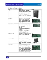
IP7[ ]-4KSU-C1
One common chassis used for the
Controlling (Main) chassis or Expansion
chassis, A maximum of three chassis
(one controlling and two expansion
chassis) can be connected by bus
connection. The Chassis has one
CPU/EXIFE slot and four universal slots.
IP7[ ]-CPU-C1
The CPU-C1 board is installed into the
CPU/EXIFE Slot in the Controlling
Chassis and controls all the functions
and operations of the SL2100 system
using the system software loaded into
the CPU-C1 memory.
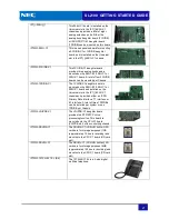
IP7WW-EXIFB-C1
The EXIFB-C1 board is installed on to
the CPU-C1 board. It is individually
connected to each EXIFE-C1 board (on
Expansion Chassis).
Supports:
• VRS/VM (InMail) channels expansion
(Up to 16ch)
•
Additional 48 Telephony resources
(DTMF/Dial tone/Busy tone/FSK
caller-ID receiver/sender)
• Support Analog Modem (V.34)
IP7WW-EXIFE-C1
The EXIFE-C1 board is installed into the
CPU/EXIFE slot on the Expansion
Chassis.
IP4WW-Battery Box
Connected to each Chassis power
supply, the external backup battery
provides DC power in case a loss of AC
power occurs. An optional (locally
provided), external battery source can
be used to provide power during a power
failure.
IP7WW-082U-B1
This 082U-B1 board is installed on the
Universal slot in the IP7[ ]-4KSU-C1
chassis and provides a total of eight
digital extension ports and two analog
extension ports. Two general purpose
relay, one Audio-In and Audio-Out ports,
are initially available. Either the analog
trunk daughter board (3COIDB) or ISDN
PRI/T1/E1 daughter board (1PRIDB)
can be mounted on this board.

