


SL2100 GETTING STARTED GUIDE
23
Chapter 2
Installation
Section 1
Before Installation
1.1
Installation Procedure
(Replacing an existing Telephone System)
The procedure below outlines the required steps for installing the SL2100.
4. Unpack all the
items and check
for damaged or
missing parts.
3. Are you replacing an existing
telephone system? If yes, consider
using the existing wiring and
installation location.
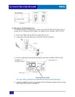
5. Mount the
SL2100 chassis
on the wall.
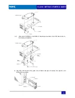
6. Insert the CPU
board and other
optional board into
the chassis.
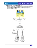
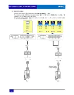
7. Consider the
wiring and connect
the telephones.
8. Connect the
Trunk lines.
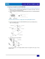
9. Consider the
power failure to
connect the
backup batteries.
10. Earth ground
connection.
13. Test the
SL2100 system.
14. Configure the
SL2100 system to
customer
’
s
requirements.
1. Confirm the
installation
location.
2. Prepare the
necessary tools,
Cables, RJ45
connectors,
…
.etc,
11. Secure the
cables.
12. Connect the
AC cord and
power up the
SL2100 system.
15. Install optional
Items.
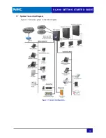
1.1.1
Confirm the Installation Location
The Installation location must be confirmed before installing the system.
AC outlet: Quantity of AC outlet, AC cord fits for the distance between Chassis and AC outlet
Weight tolerance for the wall: Material of the wall
Installation areas: enough space, temperature, humidity and other environmental requirements
Earth Ground: available
Trunk Line: available
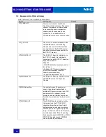
1.1.2
Prepare the necessary tolls (Not supplied)
Make sure the necessary tools (screw driver set, pliers set, etc.) are available.
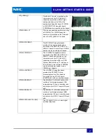
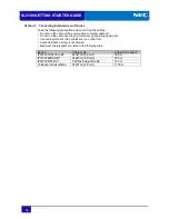
Required Items
Specification
Telephone Cables
Recommended cable type:
Twisted Pair
Conductor diameter:
0.4 to 0.6 mm
Maximum cable length (with 0.5mm diameter cable):
SL2100 system Telephone/DSS Console ---
300 meters
Analog Telephone ---
1125 meters
Cat 5 Straight Cable (or equivalent)
SL2100 IP Multiline Terminal ---
100 meters
RJ11 Plugs
Fixing Tools for RJ45 Plug and cable
2-conductor connectors for outside(CO) line


