background image

Issue 6.0

NEC SL1100

9 - 78

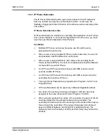
IP Multiline Station (SIP)

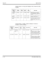
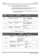
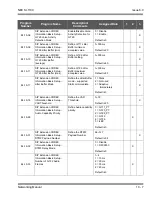
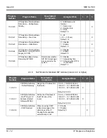
10-46-13

Subscribe Session Port

0~65535

5081

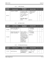
10-46-14

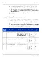
NAT Mode

Turns On/Off the NAT mode of the 
system.

0 = Off
1 = On
Default = Off

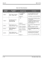
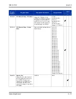
15-05-45

NAT Plug&Play

Effective when PRG 10-46-14 is 
set to NAT Mode. Select sending 
RTP port number to remote router, 
use from negotiation result (0) or 
received RTP packet (1).

0 = Off
1 = On
Default = Off

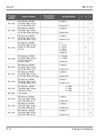
15-05-47

IP Telephone Terminal Basic 
Data Setup - Registration Expire 
Timer for NAT (V3.5 added)

On a per station basis, this setting 
defines the SIP registration expiry 
timer. This setting only applies to 
DR700 stations connected via 
NAPT. If this value is set to 0, for a 
NAPT terminal, the value in PRG 
84-23-01 is applied.

 0 = Disable
 60 ~ 65535 (sec)
 Default = 180

15-05-48

IP Telephone Terminal Basic 
Data Setup - Subscriber Expire 
Timer for NAPT 

(V3.5 Added)

On a per station basis, this setting 
defines the SIP subscribe expiry 
timer. This setting only applies to 
DR700 stations connected via 
NAPT. If this value is set to 0, for a 
NAPT terminal, the value in PRG 
84-23-02 is applied.

 0 = Disable
 60 ~ 65535 (sec)
 Default = 180

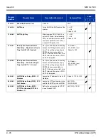
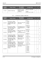
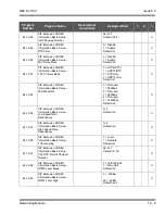
84-26-01

VoIPDB Basic Setup (DSP)– IP 
Address

Assign the IP address for the VoIP 
Gateway.

Default = 172.16.0.20

84-26-02

VoIPDB Basic Setup (DSP)– RTP 
Port Number

Assign the RTP port number to be 
used for the DSP on the VoIPDB.

VoIP GW = 
10020~10083

84-26-03

VoIPDB Basic Setup (DSP)– 
RTCP Port Number (RTP Port 
 1)

Define the port number for RTCP 
to use for each DSP.

VoIP GW = 10021

Program 

Number

Program Name

Description/Comments

Assigned Data

Level

1

2

3

Summary of Contents for SL1100

Page 1: ...Networking Manual NDA 31190 Issue 6 0 SL1100...

Page 2: ......

Page 3: ...ormation contained herein is the property of NEC Corporation and shall not be reproduced without prior written approval of NEC Corporation All other brand names and product names referenced in this do...

Page 4: ......

Page 5: ...ew 1 1 Section 2 Common Terms 1 1 Chapter 2 General Information Section 1 Voice Over IP 2 1 Chapter 3 IP Networking Section 1 Introduction 3 1 Section 2 IP Trunks 3 1 2 1 Configure IP Trunks 3 2 Chapt...

Page 6: ...ction 5 Programming Names and Text Messages 5 5 Section 6 Using Softkeys For Programming 5 6 Section 7 What the Softkey Display Prompts Mean 5 7 Section 8 Programs 5 7 10 12 CPU Network Setup 5 8 10 1...

Page 7: ...nnections xDSL Cable etc 6 6 Section 4 Firewalls and NAT 6 7 4 1 Understanding the Infrastructure 6 7 4 2 Firewall Integration 6 8 4 3 Virtual Private Network VPN Tunnelling 6 9 Section 5 CODEC and Ba...

Page 8: ...1 VoIP 7 1 Section 2 IP Networking 7 1 Section 3 SIP Trunking 7 2 3 1 Introduction 7 2 3 1 1 SIP Trunking Requirements 7 3 3 1 2 SIP Trunking Setup 7 4 Section 4 SIP Trunk Overview 7 5 4 1 General Inf...

Page 9: ...Trunk Basic Setup 7 10 6 2 IP DSP Resource 7 13 6 3 SIP Caller ID 7 15 6 4 SIP CODEC Trunk 7 16 6 5 SIP DNS Setup 7 23 6 6 SIP NAPT Router Setup 7 24 6 7 SIP System Interconnection Setup 7 24 6 8 SIP...

Page 10: ...old 9 7 Section 6 Configuration Examples 9 7 6 1 Example Configuration 1 Static IP Addressing One LAN 9 8 6 2 Example Configuration 2 Dynamic IP Addressing One LAN 9 9 6 3 Example Configuration 3 Stat...

Page 11: ...20 13 3 IP Phone Registration Modes 9 20 13 4 General IP Configuration 9 23 13 5 VLANs 9 23 13 5 1 Logging In on the PC 9 24 13 5 2 Tagging Voice Packets Using IP Phone 9 26 13 5 3 Tagging Data Packe...

Page 12: ...inals 9 73 Section 15 Conditions 9 75 Section 16 Restrictions Static NAT 9 75 Section 17 Minimum Required Programming 9 76 Chapter 10 IP Single Line Telephone Section 1 Introduction 10 1 Section 2 Pro...

Page 13: ...duction 11 1 1 2 SL1100 Requirements 11 3 1 2 1 Main Software 11 3 1 2 2 Hardware 11 3 1 2 3 Capacity 11 3 1 2 4 License 11 3 1 3 Installation 11 3 1 3 1 Settings for terminals 11 3 Section 2 Conditio...

Page 14: ..._ Issue 6 0 NEC SL1100 Section 2 System Capacity 13 3 Section 3 Network Requirements 13 4 Section 4 Quality of Service Settings QOS 13 5 Section 5 IP Precedence 13 5 Section 6 Diffserv 13 7 6 1 Condit...

Page 15: ...ntation 6 15 Figure 6 5 Priority Queuing on Voice and Data Networks 6 16 Figure 6 6 Protocol Structure for Layer 2 QoS 6 17 Figure 6 7 Layer 3 QoS Example 6 20 Figure 6 8 Common Network with Cisco Rou...

Page 16: ...oice Packets 9 39 Figure 9 22 SIP Signaling Packets 9 39 Figure 9 23 NEC SL1100 Network Example No 1 9 44 Figure 9 24 NEC SL1100 Network Example No 2 9 45 Figure 9 25 IP System Operation Setup 9 47 Fi...

Page 17: ..._______________________________________________________________________ ___________________________________________________________________________________ Figure 13 2 IP Precedence 13 6 Figure 13 3 S...

Page 18: ...__________________________________________________________________________________ ___________________________________________________________________________________ Issue 6 0 NEC SL1100 THIS PAGE IN...

Page 19: ...mes 5 5 Table 5 3 Softkey Display Prompts 5 7 Table 6 4 Type of Service Field IP Precedence i Ref REC 1349 6 22 Table 6 5 Diffserv Parameters 6 23 Table 6 6 IP Precedence and Diffserv Values Compariso...

Page 20: ..._________________________________________________________________________________ ___________________________________________________________________________________ Issue 6 0 NEC SL1100 THIS PAGE INT...

Page 21: ...SL1100 CPU CPU CPU B1 with main software CPU is shipped with KSU IP4WW VOIPDB C1 VOIPDB VOIP Daughter Board Mount this card onto the CPU card VoIPDB slot at Main KSU Max 32 channels by license control...

Page 22: ...Issue 6 0 NEC SL1100 1 2 Introduction THIS PAGE INTENTIONALLY LEFT BLANK...

Page 23: ...traffic NEC SL1100 supports the use of IP Phones These telephones provide the same functionality as a multiline telephone but use the data network rather then the traditional telecoms infrastructure...

Page 24: ...rogramming Level Adjustment Set by system programming IP Phone SIP Phone SIP Phone SIP Trunk SIP Trunk Maximum 32 Trunks DHCP Server and DHCP Client cannot be used at the same time When the DHCP Serve...

Page 25: ...t be used Refer to SIP Trunking for a a detailed description of SIP trunking and for set up instructions To set up IP trunks 1 Connect the system to the Data Network Refer to General IP Configuration...

Page 26: ...r IP Application The NEC SL1100 system now has the required information about the remote destinations and the SIP configuration is complete The only remaining task is to configure F Route to route cal...

Page 27: ...dure for connecting the NEC SL1100 system to an existing data network and configuring TCP IP This is the first step in implementing VoIP and other IP applications Enhancements With SL1100 Version 1200...

Page 28: ...ly connected to the Internet Private addresses are usually taken from the following ranges Class A 10 0 0 0 10 255 255 255 Class B 172 16 0 0 172 31 255 255 Class C 192 168 0 0 192 168 255 255 A Publi...

Page 29: ...disabled When equipment which is connected to the LAN the DHCP client is requesting an IP address it searches the DHCP server When the request for an address is recognized the DHCP server assigns an...

Page 30: ...sses for the VoIP daughter board Subnet Mask Default Gateway A spare switch First program the NEC SL1100 192 168 1 200 255 255 255 0 PRG10 12 03 192 168 1 254 A system reset is required for the IP Add...

Page 31: ...work and should be accessible by other devices on the network Refer to Figure 4 2 Example Configuration 1 Adding the NEC SL1100 KSU to the Network Figure 4 2 Example Configuration 1 Adding the NEC SL1...

Page 32: ...hen waits for a reply This test confirms that the IP addressing and physical connection are good To perform this test from a Windows PC 1 Click Start 2 Click Run 3 In the Open dialogue box enter comma...

Page 33: ...program are also included When you first install the system it uses the Default Setting for all programs Along with the Description are the Conditions which describe any limit or special consideration...

Page 34: ...ions are being set for the extension The second row of the display KY01 01 indicates that Key 01 is being programmed with the entry of 01 The third row allows you to move the cursor to the left or rig...

Page 35: ...the CD CP00 US and using Program 90 03 save the software to the Compact Flash Program 90 04 is used to reload the customer data if necessary Note that a Compact Flash can hold only one customer datab...

Page 36: ...w program beginning with 1 Pressing Mute one last time brings you to the beginning program display allowing you to enter any program number DND Switch between the different input data fields by pressi...

Page 37: ...able e g Common Permit Table If you enter data and then press this key the system accepts the data before scrolling backward Table 5 1 Keys for Entering Data Continued Keys for Entering Data Use this...

Page 38: ...ou are in the system programming Simply press the Softkey located below the option you wish and the display will change accordingly Pressing the VOLUME or VOLUME will scroll between the menus Clear Ba...

Page 39: ...k and to configure the VoIP functions Table 5 3 Softkey Display Prompts Softkey Display Prompts If you press this Softkey The system will back Go back one step in the program display You can press VOL...

Page 40: ...0 0 240 0 0 0 254 0 0 0 255 192 0 0 255 248 0 0 255 255 0 0 255 255 224 0 255 255 252 0 255 255 255 128 255 255 255 240 255 255 255 254 192 0 0 0 248 0 0 0 255 0 0 0 255 224 0 0 255 252 0 0 255 255 1...

Page 41: ...Half Duplex 0 NIC Auto Negotiate CPU 06 NAT Router Setup 0 No Disable 1 Yes Enable 0 If using an external NAT Router or not 07 NAPT Router IP Address Default Gateway WAN 0 0 0 0 126 255 255 254 128 0...

Page 42: ...5 240 0 0 255 248 0 0 255 252 0 0 255 254 0 0 255 255 0 0 255 255 128 0 255 255 192 0 255 255 224 0 255 255 240 0 255 255 248 0 255 255 252 0 255 255 254 0 255 255 255 0 255 255 255 128 255 255 255 19...

Page 43: ...t Protocol VoIP Program 10 System Configuration Setup 10 13 In DHCP Server Setup Level SA Input Data Item No Item Input Data Default Description 01 DHCP Server Mode 0 Disable 1 Enable 0 Enable Disable...

Page 44: ...em No Item Input Data Default Related Program 01 The range of the IP address to lease When Maximum has not been entered the maximum value equals the minimum value When Single is selected in 10 13 04 o...

Page 45: ...ure Cross Reference Voice Over Internet Protocol VoIP Program 10 System Configuration Setup 10 15 Client Information Setup Level SA Input Data Client Number 1 16 Item No Item Input Data Default 01 The...

Page 46: ...02 DNS Server Set IP address of DNS Server Code number 0 255 6 Fixed IP address 0 0 0 0 126 255 255 254 128 0 0 1 191 255 255 254 192 0 0 1 223 255 255 254 0 0 0 0 03 TFTP Server Set the name for the...

Page 47: ...192 0 0 1 223 255 255 254 0 0 0 0 11 Config File Name Set a File Name used for AutoConfig Code number 0 255 43 Fixed Sub code number 151 Maximum 15 character strings No setting 12 Vender Class ID Cod...

Page 48: ...255 254 0 0 0 0 21 LDS Server 2 Code number 0 255 162 Fixed IP address 0 0 0 0 126 255 255 254 128 0 0 1 191 255 255 254 192 0 0 1 223 255 255 254 0 0 0 0 22 LDS Server 3 Code number 0 255 162 Fixed I...

Page 49: ...NEC SL1100 Issue 6 0 Networking Manual 5 17 Conditions None Feature Cross Reference Voice Over Internet Protocol VoIP...

Page 50: ...gram 10 System Configuration Setup 10 19 VoIP DSP Resource Selection Level SA Input Data Slot Number 0 Input Data DSP Resource Number 01 32 Input Data Item No Item Input Data Default 01 VoIP DSP Resou...

Page 51: ...name Feature Cross Reference None Program 10 System Configuration Setup 10 62 NetBIOS Setting Level IN Input Data Item No Item Input Data Default Description 01 NetBIOS MODE 0 Disabled 1 Enabled 1 Wi...

Page 52: ...ence None Program 10 System Configuration Setup 10 63 DHCP Client Setting Level IN Input Data Item No Item Input Data Default Description 01 DHCP Client Mode 0 Disable 1 Enable 1 If you are using IP P...

Page 53: ...F FF FF 00 00 00 00 00 00 MAC Address of registered MLT SIP phone is stored and or can input the MAC address of an MLT SIP phone so when it comes online it will be provided with the extension in which...

Page 54: ...24 Button without 8LK Unit 3 Not Used 4 Not Used 5 Softphone 6 CTI 7 Not Used 8 Not Used 9 IP4WW 24TIXH 0 27 Personal ID Index 0 128 0 Use when the SIP Multiline telephone is using manual auto regist...

Page 55: ...ts the protocol mode for the Paging function 39 CTI Override Mode 0 Disable 1 Enable 0 40 Calling Name Display Info via Trunk for Standard SIP 0 Both name and number 1 Name only 2 Number only 3 None 0...

Page 56: ...Issue 6 0 NEC SL1100 5 24 Programming Conditions 15 05 04 Nickname must be unique in the system Feature Cross Reference None Voice Over Internet Protocol VoIP...

Page 57: ...s System programming must be exited before these program options take affect Feature Cross Reference Voice Over Internet Protocol VoIP Program 84 Hardware Setup for VoIP 84 09 VLAN Setup Level IN Inpu...

Page 58: ...a is set to 1 Item No 07 is invalid When Data is set to 2 Item No 02 06 are invalid 02 Priority IP Precedence 0 7 0 Low 7 High 0 1 Router queuing priority 03 IP Precedence Delay 0 1 0 Normal Delay 1 L...

Page 59: ...NEC SL1100 Issue 6 0 Networking Manual 5 27 Conditions The system must be reset for these program options to take affect Feature Cross Reference Voice Over Internet Protocol VoIP...

Page 60: ...IP telephone from the system Conditions None Feature Cross Reference Voice Over Internet Protocol VoIP Program 90 Maintenance Program 90 23 Deleting Registration of IP Telephones Level IN Input Data...

Page 61: ...eature Cross Reference None Program 90 Maintenance Program 90 34 Firmware Information Level IN Input Data Slot No 0 9 Item No Item Display Data 01 Pkg Name PKG Name 02 Firmware Version Number 00 00 0F...

Page 62: ...Issue 6 0 NEC SL1100 5 30 Programming THIS PAGE INTENTIONALLY LEFT BLANK...

Page 63: ...bes the problems that can occur and some possible solutions Each network equipment manufacturer NEC 3Com Cisco etc has slightly different methods of implementing QoS and these are not discussed in thi...

Page 64: ...time is needed to analyze the packet header check the routing table and route the packet to the output port This delay depends on the architecture of the switches routers and the size of the routing t...

Page 65: ...IP voice call The user can increase the available bandwidth to slightly exceed the 90Kbps requirements and their voice quality dramatically increases This solution might not be viable if no more bandw...

Page 66: ...vity is very light only 20Kbps or so during most of the day but does spike to 50Kbps during certain points of the day This data is not time sensitive like the voice data so if necessary it could be fo...

Page 67: ...ongestion management and bandwidth allocation By setting IP Precedence levels on incoming traffic and using them in combination with QoS queuing features you can create differentiated service Refer to...

Page 68: ...ifies the number of users subscribed to a single connection to the Internet Service Provider ISP This indicates how many users share the bandwidth with other users on the Internet which means that the...

Page 69: ...onnected to the network The network was built to be as a best effort delivery mechanism where delay and lost of information between devices was something we dealt with Today there is an over saturatio...

Page 70: ...e specified security criteria Proxy Server Proxy server intercepts all messages entering and leaving the network The proxy server effectively hides the true network address What should be noted is tha...

Page 71: ...ions such as Remote User to Corporate Site VPN Allows employees to use their local ISP fastest connection such as cable modems DSL and ISDN For traveling users all they need to do is dial into their I...

Page 72: ...address translation is applied to a VoIP packet the application fails and the communication path is broken VoIP packets contain the IP address information and the ports used as part of its payload Whe...

Page 73: ...th the NEC SL1100 system 5 1 CODECs CODEC COder DECoder uses the technology of encoding and decoding a signal For VoIP this specifically refers to the algorithm used to convert analog speech to digita...

Page 74: ...fore low bandwidth while maintaining good speech quality G 723 This ITU T recommendation describes a very low bit rate compression algorithm The standard describes two versions 5 3Kbps and 6 4Kbps NEC...

Page 75: ...disadvantages If there is a large packet size and a particular voice packet is lost this has a greater impact on the speech quality If a small quantity of voice frames per packet is being used the eff...

Page 76: ...able bandwidth to be reduced or the data to increase This impacts the packet delivery Consider data communication between the two computers shown in the diagram Figure 6 1 Layer 2 Diagram 802 1Q The H...

Page 77: ...priority and the voice is transmitted before the data This can have a negative impact on the data network if a lot of voice is transmitted Figure 6 4 Voice and Data Network Implementation shows how a...

Page 78: ...quipment to give priority to the packets that have been classified as voice Called Priority Queuing 6 2 Layer 2 QoS 802 1pq QoS is most commonly implemented at Layer 3 of the OSI model This layer deal...

Page 79: ...indicating that the next bit is the left most bit in the left most byte of the destination address Destination Address DA The DA field identifies which station s should receive the frame Source Addres...

Page 80: ...r the number of MAC client data bytes that are contained in the data field of the frame or the frame type ID if the frame is assembled using an optional format Data Is a sequence of bytes of any value...

Page 81: ...NEC SL1100 Issue 6 0 Networking Manual 6 19 Ethernet Frame Example Layer 2 QoS Enabled Continued...

Page 82: ...ield i e Marking the VoIP packets It is an end to end process and requires configuration on all networking devices Packet Marking is the first step in this process and is often the only step that the...

Page 83: ...f a 3 bit field of which the two low order least significant bits control fragmentation The low order bit specifies whether the packet can be fragmented The middle bit specifies whether the packet is...

Page 84: ...management and bandwidth allocation By setting IP Precedence levels on incoming traffic and using them in combination with QoS queuing features you can create differentiated service Table 6 4 Type of...

Page 85: ...e the priority which provides up to 64 possible values The combination of binary digits is known as the Diffserv Codepoint DSCP The example below shows an Ethernet Frame containing one RTP speech pack...

Page 86: ...ts It is possible to have the same ToS value for either method which means that the two methods can work alongside each other For example if the VoIP equipment supports IP Precedence and the router ca...

Page 87: ...7 000111 8 001000 1 Class Selector 1 9 001001 10 001010 AF11 Assured Forwarding 11 001011 12 001100 AF12 Assured Forwarding 13 001101 14 001110 AF13 Assured Forwarding 15 001111 16 010000 2 Class Sele...

Page 88: ...36 100100 AF42 Assured Forwarding 37 100101 38 100110 AF43 Assured Forwarding 39 100111 40 101000 5 Class Selector 5 41 101001 42 101010 43 101011 44 101100 45 101101 46 101110 EF Expedited Forwardin...

Page 89: ...lowest priority 6 7 2 NEC SL1100 Voice Protocols The NEC SL1100 system supports the following types of VoIP traffic 56 111000 7 Class Selector 7 57 111001 58 111010 59 111011 60 111100 61 111101 62 1...

Page 90: ...Lowest 7 Highest ToS bits 0 2 84 10 03 Delay 0 Normal 1 Low Tos Bit 3 84 10 04 Throughput 0 Normal 1 High Tos Bit 4 84 10 05 Reliability 0 Normal 1 High ToS Bit 5 ToS Bit 7 Always 0 Typically only one...

Page 91: ...example of how QoS can be implemented on a router NEC does not endorse or provide support on any third party equipment unless it is supplied by NEC See Table 6 7 Cisco Router Configuration Example fo...

Page 92: ...lass and assigns this to the VoIPPolicy 5 Allocates 50Kbps of bandwidth to the VoIPClass 6 7 Determines that any data that does not match VoIPClass should be processed using the fair queue method i e...

Page 93: ...Application IP Port Numbers Comments SIP Trunk SIP Trunk Signaling 5060 UDP SIP Trunk Voice 10020 10083 UDP 3rd Party SIP SIP SLT Signaling 5070 UDP SIP SLT Voice 10020 10083 UDP NEC Proprietary SIP...

Page 94: ...Issue 6 0 NEC SL1100 6 32 Network Design Considerations THIS PAGE INTENTIONALLY LEFT BLANK...

Page 95: ...wide area network or they can be sent over the Internet using CO lines to another gateway 1 SECTION 2 IP NETWORKING IP Networking uses VoIP technology to connect two or more telephone systems togethe...

Page 96: ...from servers then sets call parameters at either end of the communication handles call transfer and terminates The NEC SL1100 system implementation and programming for SIP are very similar The call r...

Page 97: ...SIP Trunking If entries are made in Program 10 29 xx for a SIP Server and the SIP Server is then removed or not used the entries in Program 10 29 xx must be set back to their default settings Even if...

Page 98: ...CPU B1 VOIPDB daughter board link down Lack of VOIPDB DSP resource Lack of bandwidth 3 1 2 SIP Trunking Setup Use the following steps to initially set up SIP Trunking for the NEC SL1100 system 1 By de...

Page 99: ...SIP server A maximum number of 32 SIP trunks can be used with the NEC SL1100 system The maximum number of simultaneous VoIP calls is determined by the number of resources available on the VoIPDB The N...

Page 100: ...system cannot respond to the message correctly Support the 401 407 response for the Invite of Session Timer If 401 407 response is sent for the invite of Session Timer the system can send the Invite m...

Page 101: ...ich occurs in connection with lost or delayed IP packets SECTION 5 SUPPORTED SIP TRUNKING FUNCTIONS The functions in this section are supported by NEC SL1100 SIP Trunking 5 1 Address Resolution If usi...

Page 102: ...utgoing calls on SIP trunks 5 4 Carrier Support If a common carrier supports SIP the NEC SL1100 can connect the SIP Carrier the outgoing call to the PSTN network the common IP network via an NEC SL110...

Page 103: ...SL1100 SIP trunks support Type of Service ToS Program 84 10 ToS Setup protocol type 6 SIP Trunk 5 9 Registration 5 9 1 Registration Process When the NEC SL1100 system registers its own IDs with an ext...

Page 104: ...aximum Default not assigned Version 5 0 or higher Select SIP Profile 1 2 Define the Host name This information is generally provided by the SIP carrier 10 28 03 SIP System Information Setup Transport...

Page 105: ...Carrier R 19 Carrier S 20 Carrier T 21 Carrier U 22 Carrier V 23 Carrier W 24 Carrier X 25 Carrier Y 26 Carrier Z Default 0 Version 5 0 or higher Select SIP Profile 1 2 Define the SIP Carrier Choice...

Page 106: ...d dial tone if no VRS installed 2 DISA 3 DID 4 DIL 5 Tie line 6 Delayed VRS 7 ANI DNIS 8 DID Mode Switching Default 0 Define the SIP trunks as type 3 DID In addition to the SIP trunk programming refer...

Page 107: ...0 H 323 1 SIP Default 1 Assign each trunk type for each DSP Resource 10 19 01 VoIP DSP Resource Selection VoIP DSP Resource Selection 0 Commonly used for both IP Extensions and Trunks 1 Use for IP Ext...

Page 108: ...e for the trunk you are programming Second dial tone for option 1 if no VRS is installed 84 26 01 IPL Basic Setup IP Address XXX XXX XXX XXX Assign the VOIPDB Gateway IP Address VoIP GW Number 1 172 1...

Page 109: ...equal up to 16 digits Default not assigned This program assigns the Caller Party Number for each IP trunk The assigned number is sent to the central office when the caller places an outgoing call If t...

Page 110: ...Default is 0 Version 5 0 or higher Select SIP Profile 1 2 Enable Disable the G 711 VAD Detection Mode 84 13 03 SIP Trunk CODEC Information Basic Setup G 711 Type 0 A law 1 law Default is 1 Version 5 0...

Page 111: ...r 84 13 08 SIP Trunk CODEC Information Basic Setup G 729 Voice Activity Detection Mode 0 Disable 1 Enable Default is 0 Version 5 0 or higher Select SIP Profile 1 2 Enable Disable the G 729 VAD Detecti...

Page 112: ...or higher Select SIP Profile 1 2 Set the minimum value of the G 723 Jitter Buffer 84 13 15 SIP Trunk CODEC Information Basic Setup G 723 Jitter Buffer Standard 0 300ms Default is 60 Version 5 0 or hig...

Page 113: ...reshold 84 13 28 SIP Trunk CODEC Information Basic Setup Audio Capability Priority 0 G 711_PT 1 G 723_PT 2 G 729_PT 3 G 722_PT 4 G 726_PT 5 iLBC 6 G 711 Only 7 G 729 Only Default is 0 Version 5 0 or h...

Page 114: ...10ms 2 20ms 3 30ms 4 40ms Default is 3 Version 5 0 or higher Select SIP Profile 1 2 84 13 35 SIP Trunk CODEC Information Basic Setup G 722 Jitter Buffer min 0 255ms Default is 30 Version 5 0 or highe...

Page 115: ...t is 0 Version 5 0 or higher Select SIP Profile 1 2 84 13 40 G 726 Jitter Buffer min 0 255ms Default is 30 Version 5 0 or higher Select SIP Profile 1 2 84 13 41 G 726 Jitter Buffer average 0 255ms Def...

Page 116: ...s 1 Version 5 0 or higher Select SIP Profile 1 2 84 13 52 SIP Trunk CODEC Information Basic Setup FAX Maximum Rate 1 4800bps 3 9600bps 5 14400bps Default is 5 Version 5 0 or higher Select SIP Profile...

Page 117: ...election Assigned Data Comments Program Item No Description Selection Assigned Data Comments 10 29 08 SIP Server Information Setup DNS Server Mode 0 Off 1 On Default is 0 Version 5 0 or higher SIP Pro...

Page 118: ...2 07 CPU Network Setup NAPT Router IP Address 0 0 0 0 126 255 255 254 128 0 0 1 191 254 255 254 192 0 0 1 223 255 255 254 Default is 0 0 0 0 Set the NAPT Router IP address With SIP trunking the IP add...

Page 119: ...Description Selection Assigned Data Comments 84 14 06 SIP Trunk Basic Information Setup SIP Trunk Port Number 1 65535 Default is 5060 Profile 1 5062 Profile 2 Version 5 0 or higher Select SIP Profile...

Page 120: ...lt Proxy Outbound 0 Off 1 On Default is 0 Version 5 0 or higher Select SIP Profile 1 2 Define the SIP Proxy setup Default Proxy Outbound When SIP trunking is used this must be on If entries are made i...

Page 121: ...ofile 1 2 Define the Proxy Port Number 10 29 12 SIP Server Information Setup Proxy Domain Name 64 characters maximum Default not assigned Version 5 0 or higher Select SIP Profile 1 2 Define the Proxy...

Page 122: ...60 Version 5 0 or higher Select SIP Profile 1 2 Define the Registrar Port Numbers 10 29 11 SIP Server Information Setup Registrar Domain Name 128 characters maximum Default not assigned Version 5 0 or...

Page 123: ...program also assigns whether or not the alarm is displayed to a key telephone and whether or not the alarm information is reported to the predefined destination Define alarms 14 and 60 Program Item N...

Page 124: ...Program Item No Description Selection Assigned Data Comments 10 37 01 UPnP Setup UPnP Mode 0 Disable 1 Enable Default is 0 Determine whether UPnP Universal Plug and Play task starts If UPnP task start...

Page 125: ...configured to provide the system the same IP address every time For example in the DHCP server extend the lease time to infinite or setup the server to provide the same IP address based on the system...

Page 126: ...P Address from the DHCP Server the system uses the IP Address assigned in PRG 10 12 After the IP Address and Subnet Mask are set if different IP Addresses or Subnet Mask is delivered during normal ope...

Page 127: ...igns the IP address of the CPU card 192 168 0 10 10 12 02 Subnet Mask CPU Assigns the Subnet Mask of the CPU card 255 255 255 0 10 12 03 CPU Network Setup Default Gateway Assign the default gateway IP...

Page 128: ...255 192 0 0 255 224 0 0 255 240 0 0 255 248 0 0 255 252 0 0 255 254 0 0 255 255 0 0 255 255 128 0 255 255 192 0 255 255 224 0 255 255 240 0 255 255 248 0 255 255 252 0 255 255 254 0 255 255 255 0 255...

Page 129: ...The example below shows the necessary steps to add options to a Windows 2003 server so that the server will provide the IP Address of the SL1100 PRG 10 12 09 1 In the DHCP Server right click on the a...

Page 130: ...indow pops up Select Add to create the new entry for the SL1100 system Once the option type window is available assign the following information Name SIP Server Data Type Binary Code 120 Description A...

Page 131: ...ue 6 0 Networking Manual 8 7 3 In the DHCP server select the scope of options for the DHCP scope that is being configured Right click on the Scope Options and select Configure Options Figure 8 3 DHCP...

Page 132: ...d place a check mark next to 120 SIP Server Once the server is added the data field needs to be changed In the Data Entry default delete the default value 00 and add the IP address of the SL1100 syste...

Page 133: ...erver Listed is an example of what data is to be entered 01 1st SIP Server AC Hex for 172 10 Hex for 16 00 Hex for 0 0A Hex for 10 This tells the system that the first SIP server s IP address is 172 1...

Page 134: ...Issue 6 0 NEC SL1100 8 10 DHCP Client THIS PAGE INTENTIONALLY LEFT BLANK...

Page 135: ...d from IP to TDM Time Division Multiplexing technology The VoIPDB daughter board provides this function It is possible for DR700 IP Phones to talk directly to other DR700 IP Phones without using a VoI...

Page 136: ...es in the same way as a digital multiline telephone It has all features and flexibility you expect from a digital multiline telephone The difference is that the IP telephone has an RJ 45 for connectio...

Page 137: ...ent squared key system The same Virtual Extension assignment Paging key with LED ON assignment The same location Park key The same BLF key assignment Day Night Mode Change key assignment The same VM M...

Page 138: ...nd switch hub port If installing an IP telephone at a location that already has a PC connected to the data network it is possible to use either of the following methods Use a different cable and compl...

Page 139: ...The IP telephone has a connector for external power This is supplied by an AC adapter that outputs 27V DC This means that a power outlet is required in the vicinity of each IP Phone and loss of power...

Page 140: ...occur if the following occurs Peer To Peer call receives a Barge In without a Barge In tone Peer To Peer call receives a Barge In with Monitor mode Established Barge In is disconnected The Peer to Pee...

Page 141: ...4 26 02 IPL Basic Setup RTP Port Number Enter the RTP port number range 5 1 Music on Hold Music on Hold is provided by the IP telephone The settings in Program 10 04 Music on Hold Setup are ignored ex...

Page 142: ...ected to a single LAN no routers with static IP Addresses Figure 9 3 Example Configuration 1 Static IP Addressing One LAN IP4 VoIP Switch NEC SL1100 VoIPDB IP Address 192 168 1 20 VoIP Gateway 192 168...

Page 143: ...CPU 10 12 01 CPU Network Setup IP Address for CPU 10 12 10 CPU Network Setup Subnet M ask 10 12 03 CPU Network Setup Default Gateway 10 12 09 CPU Network Setup VoIPDB IP Address This assignment is fo...

Page 144: ...the VoIP daughter board is installed 10 13 01 In DHCP Server Setup DHCP Server Mode 10 14 01 Managed Network Setup Scope 1 0 0 0 0 255 255 255 0 192 168 1 254 192 168 1 20 On 192 168 1 200 Min 192 168...

Page 145: ...g This is a typical scenario a small branch office connecting to the main office Figure 9 5 Example Configuration 3 Static IP Addressing Routed WAN CPU VoIP Switch IP Phone 1 192 168 2 200 IP Phone 2...

Page 146: ...ones either of these options requires the DHCP server to be configured to supply the IP terminal options If using the internal DHCP server enable the DHCP server Refer to 6 2 Example Configuration 2 D...

Page 147: ...TY OF SERVICE NEC recommends configuring Quality of Service QoS to ensure that the speech quality is not affected by other data on the network QoS is discussed further in Network Design Considerations...

Page 148: ...cast domain 9 1 1 Programming Layer 2 Priority Control To program Layer 2 Priority Control for IP Phones VLAN QoS 1 Press the Menu button on the IP Phone to enter the telephone program mode This enter...

Page 149: ...erv 84 10 07 ToS Setup Priority D S C P Differentiated Services Code Point For the Protocol type 1 Not Used 2 Not Used 3 Voice Control 4 Not used 5 RTP RTCP 6 SIP 7 Not used 8 DR700 MLT 9 SIP Trunk 10...

Page 150: ...rformance Digital ISDN T 1 and SIP trunks do not suffer from this problem When analog trunks are installed in an SL1100 PRG 90 68 Side Tone Auto Setup must be used This program will automatically chan...

Page 151: ...on 1 Download File 9 To boot the program press 2 Boot Program 10 Press the softkey The IP Phone downloads the firmware from the FTP TFTP server and reboots when the download is complete 12 2 Checking...

Page 152: ...ile name itlisipr tgz 5 In Program 90 42 assign the software and hardware versions An example of the hardware assignment would be 09 01 03 06 this is Hardware Version 9 1 3 6 SECTION 13 IP STATION SIP...

Page 153: ...aces directly to the CPU that houses the VoIPDB daughter board The VoIPDB provides the digital signal processors DSPs for IP stations and trunks VoIPDB provides 32 DSPs A DSP provides format conversio...

Page 154: ...Feature The DHCP server can provide the SL1100 with the following information IP Address for VoIPDB PRG 10 12 09 Subnet Mask for VoIPDB PRG 10 12 10 Default Gateway for VoIPDB PRG 10 12 03 The DHCP se...

Page 155: ...sword or extension number is entered into the configuration of the telephone The user is prompted to enter this user name and password into the IP phone This information is cross referenced in the pho...

Page 156: ...ice leaves the SL1100 to third party SIP terminal the voice cannot be encrypted DR700 DR700 S DR700 PSTN S The encryption will be between the IP terminal and the VoIPDB Once the voice leaves the SL110...

Page 157: ...an IP ready check and a site survey must be completed at each site before VoIP implementation One way delay must not exceed 100ms Round trip delay must not exceed 200ms Packet loss must not exceed 1 D...

Page 158: ...he tag numbers the higher the priority However this is left up to the network administrator as they could set the exact opposite where the lower tag numbers have a higher priority Tagging Voice and Da...

Page 159: ...NEC SL1100 Issue 6 0 Networking Manual 9 25 Figure 9 7 Log In to IP Phone...

Page 160: ...e Packets Using IP Phone 1 To apply a tag to the voice packets only go to Network Settings Advanced Settings LAN port settings 2 Access the following three menus to select options for LAN Port Setting...

Page 161: ...VLAN ID allows an entry of 1 4094 for the VLAN ID VLAN Mode must be enabled for this entry to be valid Enter the VLAN ID and click OK 6 VLAN Priority allows an entry of 0 7 for the VLAN Priority VLAN...

Page 162: ...o the IP address of the phone on the PC go to Network Settings Advanced Settings PC Port Settings Refer to Section 13 5 1 Logging In on the PC on page 9 24 2 Access the following three menus to select...

Page 163: ...re the same as those for the voice packets 5 VLAN ID allows an entry of 1 4094 for the VLAN ID VLAN Mode must be enabled for this entry to be valid Enter the VLAN ID and click OK 6 VLAN Priority allow...

Page 164: ...SL1100 9 30 IP Multiline Station SIP 7 Click Save 8 After saving settings click OK to confirm Telephone reboots and applies the VLAN settings Figure 9 16 Save Network Settings Figure 9 17 Save Confir...

Page 165: ...N ID of 1 4094 Press the OK soft key after the setting is changed 10 Press 4 on the dial pad for VLAN Priority 11 Enter the VLAN priority of 0 7 Press the OK soft key after the setting is changed 12 I...

Page 166: ...circumstances the higher the number the higher the priority However this is left to the network administrator for setup The administrator may assign this in exactly the opposite manner with the lower...

Page 167: ...ues and their associated names IP Precedence IP Precedence IP Precedence Delay Throughput Reliability Cost Not Used 1 on here value of 4 1 on here value of 2 1 on here value of 1 DSCP Code Points Bina...

Page 168: ...s setting data affects only the packets sent by the VoIPDB card This does not affect the packets sent from the IP terminals 101110 46 Expedited Forwarding EF 110000 48 Class Selector 6 CS6 111000 56 C...

Page 169: ...use the same ToS value this can be assigned in commands 84 23 06 and 84 23 12 When an IP phone registers with the CPU it looks for settings in these commands If these are found they override any prev...

Page 170: ...signaling packets an IP precedence value of 4 and the voice packets an IP precedence value of 5 it would be as follows Refer to Figure 9 19 SIP MLT Basic Setup 80 in Hex is 10000000 This represents t...

Page 171: ...decimal Equivalent IP Precedence Name Hex Value IP Precedence 1 20 IP Precedence 2 40 IP Precedence 3 60 IP Precedence 4 80 IP Precedence 5 A0 IP Precedence 6 C0 IP Precedence 7 E0 DSCP Name Hex Value...

Page 172: ...enter the values per phone browse to the individual phone or enter the configuration mode through dial pad The following example describes assigning these fields via the web browser 1 Log in on PC Re...

Page 173: ...decimal Equivalent on page 9 37 Access the following menus to select options RTP Voice Packets SIP Signaling Packets 4 After selecting Save the following message appears 5 Select OK and the phone rebo...

Page 174: ...ia CODEC Packet Size RTP Header Compression Voice Activity Detection VAD Number of simultaneous calls Layer 2 media is concerned with moving data across the physical links in the network A few of the...

Page 175: ...ations are packetized and sent including silence On an average a typical conversation contain anywhere from 35 45 silence This can be interrupted as 35 45 transmission of VoIP packets as having no aud...

Page 176: ...ernet 18 Bytes 802 1Q P Ethernet up to 32 bytes PPP 9 Bytes Frame Relay 6 Bytes Multilink Protocol 6 Bytes Bandwidth Calculation Layer 2 overhead IP UDP RTP header Voice Payload Voice Payload Default...

Page 177: ...all A firewall is filtering software built into a router or a stand alone server unit It is used to protect a LAN it from unauthorized access providing the network with a level of security Firewalls a...

Page 178: ...the NEC equipment thus blocking them and resulting in registration failure To solve this issue the ports used by the NEC VoIP equipment must be opened in the firewall allowing the NEC traffic to pass...

Page 179: ...AIN location The following diagram shows three sites connected together via VPN This network is not fully meshed due to the lack of a VPN tunnel between Sites B and C With Peer to Peer enabled the IP...

Page 180: ...point the two IP phones attempt to send voice packets directly to each other As there is no VPN connection between these sites the call is set up with no voice path To correct this issue another VPN c...

Page 181: ...NEC SL1100 Issue 6 0 Networking Manual 9 47 Figure 9 25 IP System Operation Setup...

Page 182: ...CPU 0 0 0 0 126 255 255 254 128 0 0 1 191 255 255 254 192 0 0 1 223 255 255 254 Default is 172 16 0 10 X 10 12 10 CPU Network Setup Subnet Mask Assign Subnet Mask to the VoIPDB connected to CPU Defaul...

Page 183: ...this user ID password against Programs 84 22 15 05 27 If there is not a match the phone does not come on line 0 Plug and Play 1 Automatic 2 Manual Default is 0 X 10 46 04 DR700 Server Information Set...

Page 184: ...3 READ ONLY X 15 05 02 IP Telephone Terminal Basic Data Setup Terminal MAC Address Allow association of a MAC Address to an extension When the IP phone sends a register message to the CPU the CPU resp...

Page 185: ...ex When complete go to command 84 22 and set the user name and password 0 Not Set 1 128 Set Default is 0 X 15 05 28 IP Telephone Terminal Basic Data Setup Additional Information Setup 0 Disable 1 Enab...

Page 186: ...the Paging function 0 Multicast 1 Unicast 2 Auto Default is 0 X 15 05 39 IP Telephone Terminal Basic Data Setup CTI Override Mode 0 Disable 1 Enable Default is 0 X 15 05 40 IP Telephone Terminal Basic...

Page 187: ...egistration Program 10 46 01 Assign up to 32 Alpha Numeric Characters Default is No Setting X 84 22 02 DR700 Multiline Logon Information Setup Password Password for Manual or Auto registration Program...

Page 188: ...or duration of this timer and then is disconnected Range 0 65535 Sec Default is 180 X 84 23 06 DR700 Multiline Basic Information Setup Signal Type of Service Used for updating the IP terminals SIGNALI...

Page 189: ...o contact the network administrator this number is dialed Up to 32 Digits 0 9 P R Default is No Setting X 84 23 13 DR700 Multiline Basic Information Setup Media Type of Service Assign the IP terminals...

Page 190: ...he dynamic jitter buffer Range 0 255ms Default is 80 X 84 24 07 DR700 Multiline CODEC Basic InformationSetup Number of G 729 Audio Frames Amount of audio in each RTP packet Range 1 4 1 10ms 2 20ms 3 3...

Page 191: ...84 24 28 DR700 Multiline CODEC Basic InformationSetup Audio Capability Priority This assign the CODEC to be used Range 0 3 0 G 711_PT 1 Not Used 2 G 729_PT 3 G 722_PT Default is 0 X 84 24 30 DR700 Mu...

Page 192: ...iline CODEC Basic InformationSetup G 722 Jitter Buffer Maximum Maximum value of the dynamic jitter buffer Range 0 255ms Default is 120 X 84 28 01 DR700 Multiline Firmware Name Setup Firmware Directory...

Page 193: ...0 12 Assign the VoIPDB registration signaling IP address subnet mask and default gateway If no customer provided default gateway is provided leave Gateway IP address at 0 0 0 0 2 Program 84 26 Assign...

Page 194: ...ng with the higher number ports By default all Station Ports are assigned numbers in the SL1100 These are easily changed in Program 11 02 to the required station number as long as the leading digit di...

Page 195: ...is step is optional To enable Key data and other station feature programming before IP Phone is brought online the extensions must be identified as IP Phones Once checked in the IP Phone List in PC Pr...

Page 196: ...with a User Name and Password These are the defaults User Name ADMIN Password 6633222 The user name should already be entered in the terminal Press Set soft key to step down to the password field Afte...

Page 197: ...teps 1 3 are the same as for Plug and Play mode Step 4 is not optional and MUST be assigned when using Automatic Registration 2 Same as Plug and Play mode 3 Same as Plug and Play mode 4 To enable key...

Page 198: ...nge Program 10 46 01 to Automatic 6 Program 15 05 27 Each IP phone requires a unique personal ID index Valid settings are 1 512 Figure 9 31 DR700 Server Information Setup Figure 9 32 Automatic Registr...

Page 199: ...e in the station using the following steps The station does not require an Ethernet connection to enter the program mode Only power is required Power can be provided by an AC adapter plugged into the...

Page 200: ...click OK If you are testing without a router gateway this must be left at the default 0 0 0 0 Subnet Mask Enter the Subnet Mask for the station and click OK SIP Settings SIP User User ID Enter User ID...

Page 201: ...matic Registration Mode 7 Same as for Automatic Registration Mode 8 The SIP MLT Station requires assignments to be made in the phone itself Enter the Program Mode in the station using the following st...

Page 202: ...f you are testing without a router gateway this must be left at the default 0 0 0 0 Subnet Mask Enter the Subnet Mask for the station and click OK SIP Settings Do not enter any information in the SIP...

Page 203: ...I mode and controlling the IP Phone by this SoftPhone the user ID and password should be different for the SoftPhone and IP Phone An IP Phone IP Phone and Soft phone with DSS console cannot override a...

Page 204: ...is using manual auto registration Assign each phone a unique personal index Then go to command 84 22 to assign the user name and password 84 22 01 DR700 Multiline Logon Information Setup User ID Up t...

Page 205: ...d of the connection if required Enhancements With SL1100 V3 5 or higher the NAPT feature is enhanced Previously when the DR700 connects to the system via NAPT the intermediate router firewall could po...

Page 206: ...Issue 6 0 NEC SL1100 9 72 IP Multiline Station SIP Figure 9 36 NAPT Configuration Example...

Page 207: ...ADMIN and password is 6633222 NEC 14 3 1 Settings for terminals Setting location 0 Config 2 SIP Settings 8 NAT Traversal Number and Name of Setting Setting Value Default Value Factory Value Auto Conf...

Page 208: ...6 3 WAN Self IP Address IP Address 0 0 0 0 Available Available Only used when Static NAT is enabled This setting is the WAN address of the router that the NAPT Terminal resides behind Number and Name...

Page 209: ...al public IP address When Program 10 46 14 is set to ON it references programs 10 58 01 and 10 58 02 These programs are used to define any destination networks that do not get sent through the NAPT tr...

Page 210: ...his feature Level 2 these are the next most commonly assigned programs for this feature Level 3 these programs are not often assigned and require an expert level working knowledge of the system to be...

Page 211: ...0 0 252 0 0 0 254 0 0 0 255 0 0 0 255 128 0 0 255 192 0 0 255 224 0 0 255 240 0 0 255 248 0 0 255 252 0 0 255 254 0 0 255 255 0 0 255 255 128 0 255 255 192 0 255 255 224 0 255 255 240 0 255 255 248 0...

Page 212: ...lue in PRG 84 23 01 is applied 0 Disable 60 65535 sec Default 180 15 05 48 IP Telephone Terminal Basic Data Setup Subscriber Expire Timer for NAPT V3 5 Added On a per station basis this setting define...

Page 213: ...ks Registered SIP stations and or SIP trunks require a one to one relation with the VoIPDB DSP Resource This is a required component of SIP implementation in the NEC SL1100 The NEC SL1100 VoIPDB conta...

Page 214: ...of voice at rates of 16 24 32 and 40Kbps ILBC Internet Low Bitrate CODEC Narrow band speech ILBC enables graceful speech quality degradation in the case of lost frames which occurs in connection with...

Page 215: ...e if you had a STD SIP Terminal that had two lines registering with the same IP Address you would need to flag PRG 15 05 18 for both Extension numbers In the router firewall that the SL1100 resides be...

Page 216: ...is 0 0 0 0 X 10 12 09 CPU Network Setup IP Address Assign the IP Address of the VoIPDB 0 0 0 0 126 255 255 254 128 0 0 13 191 255 255 254 192 0 0 1 223 255 255 254 Default is 172 16 0 10 X 10 12 10 C...

Page 217: ...ption Comments Assigned Data 1 2 3 10 26 02 IP System Operation Setup RTP Forwarding Mode 0 No Disable 1 Yes Enable default is 0 X 10 26 03 IP System Operation Setup SIP Peer to Peer Mode Enable or di...

Page 218: ...oice Activity Detection for G 711 0 Disable 1 Enable Default is 0 X 84 19 03 SIP Extension CODEC Information Basic Setup G 711 Type Define the G 711 Type law is recommended in USA 0 A law 1 law Defaul...

Page 219: ...Information Basic Setup Jitter Buffer Mode Define the Jitter Buffer mode supported Static or Immediate 1 Static 2 Not used 3 Adaptive Immediately Default is 3 X 84 19 18 SIP Extension CODEC Informati...

Page 220: ...lt is 0 X 84 19 40 SIP Extension CODEC Information Basic Setup G 726 Jitter Buffer min 0 255ms Default is 30 X 84 19 41 SIP Extension CODEC Information Basic Setup G 726 Jitter Buffer Average 0 255ms...

Page 221: ...1 4800bps 2 Not used 3 9600bps 4 Not used 5 14400bps Default is 5 X 84 19 56 SIP Extension CODEC Information Basic Setup Low Speed Data Redundancy 0 2 Default is 0 X 84 19 57 SIP Extension CODEC Infor...

Page 222: ...ion Basic Information Setup Session Timer Value Define the periodic refresh time that allows both user agents and proxies to determine if the SIP session is still active 0 65535 Default is 180 X 84 20...

Page 223: ...matches MAC address 00 00 00 00 00 00 to FF FF FF FF FF FF Default is 00 00 00 00 00 00 X 15 05 07 IP Telephone Terminal Basic Data Setup Using IP Address Informational Only registered IP Phones 0 0...

Page 224: ...ages are received by the system 0 Disable 1 Allowed any time 2 Allowed while RTP is not available Default 2 Program Number Program Name Description Comments Assigned Data 1 2 3 Program Number Program...

Page 225: ...255 224 0 0 255 240 0 0 255 248 0 0 255 252 0 0 255 254 0 0 255 255 0 0 255 255 128 0 255 255 192 0 255 255 224 0 255 255 240 0 255 255 248 0 255 255 252 0 255 255 254 0 255 255 255 0 255 255 255 128...

Page 226: ...trar Proxy Information Basic Setup NAT Mode When system controls remote SIP phone via NAT router set this program to 1 Enable 0 No Disable 1 Yes Enable default is 0 X 10 37 01 UPnP Setup UPnP Mode Def...

Page 227: ...esides behind Effective only when PRG 10 46 14 is set to 1 Enable 0 No Disable 1 Yes Enable default is 1 X 15 05 47 IP Telephone Terminal Basic Data Setup Registration Expire Timer for NAT On a per st...

Page 228: ...65534 Default for DSP1 is 10020 X 84 26 03 VoIPDB Basic Setup RTCP Port Number Assign the RTCP Port Number 0 65535 Default for DSP1 is 10020 10083 X Program Number Program Name Description Comments As...

Page 229: ...100 Issue 6 0 Networking Manual 10 17 2 3 SIP Phone Example SIP Phone VoIP Switch NEC SL1100 VoIPDB 192 168 1 20 VoIPDB DSP 192 168 1 21 Subnet Mask 255 255 255 0 Default Gateway 192 168 1 254 SIP Sof...

Page 230: ...Issue 6 0 NEC SL1100 10 18 IP Single Line Telephone THIS PAGE INTENTIONALLY LEFT BLANK...

Page 231: ...orts are translated into a single public address and its TCP UDP ports In the case of IP phones with the SL1100 it allows their connection to a public Internet IP address which is then converted back...

Page 232: ...Issue 6 0 NEC SL1100 11 2 NAPT Figure 11 1 NAPT Configuration Example...

Page 233: ...t the terminal press HOLD TRANSFER User name is ADMIN and password is 6633222 NEC 1 3 1 Settings for terminals Setting location 0 Config 2 SIP Settings 8 NAT Traversal Number and Name of Setting Setti...

Page 234: ...0 Available Available Only used when Static NAT is enabled This setting is the WAN address of the router that the NAPT Terminal resides behind Number and Name of Setting Setting Value Default Value Fa...

Page 235: ...uired to be forwarded to the IP Terminals NAPT can be used for SIP trunks and terminals on the same system SECTION 3 RESTRICTIONS STATIC NAT With static NAT the terminal needs a static IP Address assi...

Page 236: ...ature Level 2 these are the next most commonly assigned programs for this feature Level 3 these programs are not often assigned and require an expert level working knowledge of the system to be proper...

Page 237: ...4 0 255 255 255 0 255 255 255 128 255 255 255 192 255 255 255 224 255 255 255 240 255 255 255 248 255 255 255 252 255 255 255 254 255 255 255 255 default 255 255 0 0 10 46 06 Register Port Assign the...

Page 238: ...01 VoIPDB Basic Setup DSP IP Address Assign the IP address for the VoIP Gateway Default 172 16 0 20 84 26 02 VoIPDB Basic Setup DSP RTP Port Number Assign the RTP port number to be used for the DSP on...

Page 239: ...used This can be used to trouble shoot issues or to alert when the current hardware might need to be upgraded to a higher capacity Alarm Message Format The Alarm message for will vary depending on wha...

Page 240: ...ablished due to an All DSP Busy condition the Multiline telephone will not display the All DSP busy message If a SIP trunk call is sent to the SL1100 when all DSP resources are busy the call is reject...

Page 241: ...ber Program Name Description Comments Assigned Data Level 1 2 3 20 13 52 VoIP All DSP Busy Display Set on a per station class of service basis whether the All DSP Busy alarm displays on the LCD when t...

Page 242: ...Issue 6 0 NEC SL1100 12 4 All DSP Busy Indication THIS PAGE INTENTIONALLY LEFT BLANK...

Page 243: ...he centralized attendant can receive calls from and transfer calls to any destination throughout the whole network This allows calls to route as if they were part of a single much larger system Centra...

Page 244: ...commended that each site have at least one analog trunk to dial 911 in the case of an emergency Network BLF Indication Centralized Call Park Orbits Users can see the status of other extensions through...

Page 245: ...igher the maximum capacity has increased to 256 The below example is showing a system that has a version lower than Version 3500 When the capacity is exceeded an alarm report is generated and the mess...

Page 246: ...work and Internet service providers Because these variables are not within NEC s control the performance of the users IP based voice solution cannot be guaranteed Therefore NEC recommends connecting t...

Page 247: ...ence or Diffserv Values per Protocol Type For SL Net only two protocol types will be selected All signaling packets will be marked with the values assigned for protocol type H 323 All voice packets wi...

Page 248: ...where the signaling packets are to be tagged with an IP Precedence of 4 and the voice packets are to be tagged with an IP Precedence of 5 After changes are made to Program 84 10 the system will need...

Page 249: ...100 Setting DSCP Code Point Name 0 Best Effort BE 8 Class Selector 1 CS1 10 Assured Forwarding 11 AF11 12 Assured Forwarding 12 AF12 14 Assured Forwarding 13 AF13 16 Class Selector 2 CS2 18 Assured Fo...

Page 250: ...into the IP packets 6 1 Conditions CPU software 1500 Version 1 50 or higher is required A maximum of five nodes and a total of 168 ports below Version 3500 or 256 ports Version 3500 and above total t...

Page 251: ...example if users in Class of Service 1 at site 1 want to block the Camp On feature a change will have to be made in Class of Service 1 of all systems in the network Paging to a networked system can on...

Page 252: ...oing CO calls via the network the loop key will not light If ARS is enabled and an outgoing CO call via the network is placed the loop key will light for the first few seconds until the system determi...

Page 253: ...ll is routed across the SL Net network A Secondary Incoming Extension cannot be programmed for a station in a Remote SL Net system A Secretary Call Buzzer and Secretary Call Pickup key PRG 15 07 key 4...

Page 254: ...ion performing the transfer Default Setting None SYSTEM AVAILABILITY Terminals All Terminal types are supported Required Components IP4 128M B KSU IP4WW VOIPDB C1 SL Net License SL SYS SL NET LIC RELA...

Page 255: ...ault 0 0 0 0 84 26 01 VoIP Basic Setup DSP Assign the IP address that is used for Voice Communications across the network The IP address assigned here MUST be within the same network as the IP address...

Page 256: ...digit 2 would be assigned as network ID 1 0 No Remote Network 1 Remote Network 1 2 Remote Network 2 3 Remote Network 3 4 Remote Network 4 default 0 10 27 01 Network System ID Assignment Define the IP...

Page 257: ...000 4 Networking System default 30000 5 SMDR Output default 0 6 DIM Output default 0 9 1st Party CTI default 8282 11 O M Server default 8010 12 Traffic Report Output default 0 13 Room Data Output for...

Page 258: ...When set to Each Port Mode only special SLT PRG 15 03 03 1 trunks and networking ports can use the Fax Relay 0 Disable 1 Enable 2 Each Port Mode default 0 84 12 01 G 711 Audio Frame Size Assign the G...

Page 259: ...sumed However when a smaller packet is lost in a network a smaller amount of the voice is lost with it 1 10ms 2 20ms 3 30ms 4 40ms 5 50ms 6 60ms default 3 84 12 08 G 729 Voice Activity Detection This...

Page 260: ...hen silence detection is enabled the SL1100 can detect the absence of audio and conserve bandwidth by preventing the transmission of silent packets over the network When this program is enabled it can...

Page 261: ...daptec Threshold 1 19dB 49dBm 20 0dB 30dBm 29 9dBm 21dBm 30 10dBm 20dBm default 20 84 12 33 G 722 Audio Frame Size Assign the G 722 Audio Frame Size The smaller the packet sizes the more bandwidth tha...

Page 262: ...7 01 s set to 1 inband If 84 27 01 is set to inband and this program is set to VoIPU the DTMF level follows the default value If 84 27 01 is set to inband and this program is set to Main Soft then PRG...

Page 263: ...the access code that users will dial to make outbound calls Maximum of 4 digits 0 9 default 9 11 09 02 2nd Trunk Route Access Code Use this program to assign the special trunk access code defined in...

Page 264: ...be accessed in the local system 0 No routing Calls will not route 1 25 Route table 1 25 PRG 14 06 01 default 1 15 07 01 Programmable Function Keys This program is used on a per station basis to assig...

Page 265: ...mote system 3 that is programmed in 10 27 01 104 will access trunks from Remote system 4 that is programmed in 10 27 01 If 26 02 02 is set to Trunk Group 0 No Routing Calls will not route 1 25 Trunk G...

Page 266: ...elay VRS 7 ANI DNIS 8 DID DDI Mode Switching default 0 22 07 01 DIL Assignment For each trunk and day night mode assignment designate the destination extension or pilot number where the trunk is route...

Page 267: ...07 0 No Setting 1 25 Ring Group 1 25 102 Voice Mail Call goes to the VM pilot assigned in program 45 01 01 103 Centralized Voice Mail if centralized VM is enabled this setting is used to route calls...

Page 268: ...igits entered should be equal to the setting assigned in program 22 09 01 Maximum of 8 digits 0 9 default Not Assigned 22 11 02 Target Number Enter the destination number where the DID is sent The des...

Page 269: ...e transfer operation mode is set PRG 22 11 04 and one of the conditions is met calls will overflow from the target number to the destination in this program If this was a No Answer condition calls wou...

Page 270: ...nds 22 01 07 DID Incoming Ring Group No Answer Time Use this program to assign the amount of time that a call will ring the Transfer Destination Number 1 before overflowing to TransferDestinationNumbe...

Page 271: ...ce Mail pilot number to the group that is to be used A pilot number must fall within the valid numbering plan assigned in program 11 01 01 NEC recommends that you do not use department group 01 becaus...

Page 272: ...idle extension in a circular order The priority of the extension is not used When using a department group for Voice Mail this program must be set to 0 priority 0 Normal Routing Priority 1 Easy UCD ro...

Page 273: ...he department group When using a department group for Voice Mail you must have licenses to cover every extension assigned 1 32 default 1 16 02 02 Department Group Priority Assignment This program sets...

Page 274: ...m that has the Voice Mail 0 No Voice Mail Assigned 1 32 Department Group 1 32 default 0 45 01 10 NSL Protocol All sites using the Centralized Voice Mail must enable this program for proper integration...

Page 275: ...jor Alarm or Minor Alarm tag in the report The following Alarms are suggested when troubleshooting an SL Net network Alarm 15 Network Keep Alive Alarm 17 Denial of Service Attack Alarm 57 IP Address C...

Page 276: ...e Keep Alive messages an Alarm 15 will be generated and labeled as a Warning An example of this alarm is MIN 0015 WAR 11 07 11 14 07 NW KeepAlive none ID 02 004 MIN Minor Alarm this is because the Ala...

Page 277: ...ated and labeled as an Error An example of this alarm is MAJ 0015 ERR 11 07 11 14 10 NW KeepAlive none ID 02 MAJ Major Alarm this is because the Alarm was flagged as major 0015 Alarm number 15 ERR Err...

Page 278: ...DB 10 12 10 255 255 0 0 255 0 0 0 Subnet Mask of VoIPDB 10 12 03 172 16 0 1 10 0 0 1 Default Gateway 84 26 01 172 16 0 11 10 0 0 11 DSP IP Address 11 02 01 Default Change extensions to 201 284 Extensi...

Page 279: ...ports to 69 84 11 02 01 Default Verify the InMail extension numbers are 169 184 11 07 01 Group 32 100 NA Assign the VM pilot Number to group 32 15 03 01 Ext s 169 184 DP NA Change ALL VM extensions t...

Page 280: ...he default value of 30000 assigned Port numbers other than default can be used but all sites must use the same port number If the port numbers at each location do not match or are unassigned calls wil...

Page 281: ...use the same port number If the port numbers at each location do not match or are unassigned calls will still be completed across the network however Call Park indication and retrieval will not funct...

Page 282: ...trunk access code 11 01 01 NA Digit 8X set to Individual Trunk Special Trunk Access Set the leading digit as special trunk access 11 09 02 NA 8 This assigns the special trunk access code defined in P...

Page 283: ...of paging external zone 1 in remote system 1 User goes off hook and dials 703 01 1 and begins paging When the user is finished paging go back on hook to end the page Combined Page Dial the combined p...

Page 284: ...omatic Route Selection ARS Yes Background Music No Barge In Yes Built In Automated Attendant No Call Arrival Keys Yes Call Duration Timer Yes Call Forwarding Yes Call Forwarding with Follow Me Yes Cal...

Page 285: ...nference Recording Yes Continued Dialing Yes Delayed Ringing Yes Department Calling Yes Department Step Calling Yes DHCP Client No It is recommended to disable this feature when using networking Dial...

Page 286: ...free Answerback Forced ICM Ringing Yes Headset Operation Yes Hold Yes Dual Hold is not supported across the network Hotel Motel No Hot Key Pad Yes Hotline Yes Howler Tone Service Yes Illuminated Dial...

Page 287: ...trunk resides in Name Storing Yes Navigation Key Yes Night Service No Off Hook Signaling Yes One Touch Calling Yes Operator No Paging External Yes Paging to a networked system can only be activated by...

Page 288: ...tension No Secretary Call Buzzer No Secretary Call Pickup No Security No Selectable Display Messaging Yes Selectable Ring Tones Yes Serial Call No Single Line Terminals Yes SL Desktop Suite Yes Soft k...

Page 289: ...twork Uniform Call Distribution UCD No User Programming Ability Yes Virtual Extensions Yes Network ports ICM or Trunk cannot land on the Virtual extension key Virtual Loopback Trunk No Voice Mail Inte...

Page 290: ...Issue 6 0 NEC SL1100 13 48 SL Net THIS PAGE INTENTIONALLY LEFT BLANK...

Page 291: ......

Page 292: ...SL1100 Networking Manual NEC Corporation of America Issue 6 0...

Reviews: