Issue 6.0
NEC SL1100
6 - 16
Network Design Considerations
After the router is configured for QoS, it examines incoming packets and allocates a
priority to the packet.
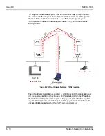
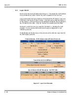
Figure 6-5 Priority Queuing on Voice and Data Networks
the affect priority queuing has on voice and data networks. The packets arrive
randomly. They are processed and output according to the QoS policy. The VoIP
traffic is output first.
To enable this type of queuing it is necessary to:
a
Configure the VoIP equipment to mark its packets with a specific value so that the
switches/routers can identify that it is voice – Called
Marking
.
b
Configure the network equipment to recognize the difference between the
different Marked packets – Called
Classification.
(i.e., informs the router what a
voice packet looks like.
c
Configure the network equipment to give priority to the packets that have been
classified as voice – Called
Priority Queuing
.
6.2
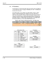
Layer 2 QoS (802.1pq)
QoS is most commonly implemented at Layer 3 of the OSI model. This layer
deals with IP addresses, and is usually handled by Routers. However,
sometimes it is necessary to implement Layer 2 QoS – usually in large LAN
environments with many IP phones.
Layer 2 devices work with Ethernet frames (encapsulated IP packets) rather
than IP addresses. Layer 2 QoS uses the Priority field of the Ethernet frame.
This field has three bits and can have eight possible values (000 to 111 in
binary). Some switches can be configured to prioritize traffic based on these
values. This field is available only if the Ethernet device is configured for
VLAN (IEEE 802.1q) operation (VLAN is outside the scope of this document).
Figure 6-5 Priority Queuing on Voice and Data Networks
Packet from VoIP Device
Packet from PC
Ethernet (100Mbps)
Leased Line (256Kbps)
Direction of IP Traffic
Router with QoS
Policy Applied
Summary of Contents for SL1100
Page 1: ...Networking Manual NDA 31190 Issue 6 0 SL1100...
Page 2: ......
Page 4: ......
Page 22: ...Issue 6 0 NEC SL1100 1 2 Introduction THIS PAGE INTENTIONALLY LEFT BLANK...
Page 62: ...Issue 6 0 NEC SL1100 5 30 Programming THIS PAGE INTENTIONALLY LEFT BLANK...
Page 94: ...Issue 6 0 NEC SL1100 6 32 Network Design Considerations THIS PAGE INTENTIONALLY LEFT BLANK...
Page 134: ...Issue 6 0 NEC SL1100 8 10 DHCP Client THIS PAGE INTENTIONALLY LEFT BLANK...
Page 159: ...NEC SL1100 Issue 6 0 Networking Manual 9 25 Figure 9 7 Log In to IP Phone...
Page 181: ...NEC SL1100 Issue 6 0 Networking Manual 9 47 Figure 9 25 IP System Operation Setup...
Page 206: ...Issue 6 0 NEC SL1100 9 72 IP Multiline Station SIP Figure 9 36 NAPT Configuration Example...
Page 230: ...Issue 6 0 NEC SL1100 10 18 IP Single Line Telephone THIS PAGE INTENTIONALLY LEFT BLANK...
Page 232: ...Issue 6 0 NEC SL1100 11 2 NAPT Figure 11 1 NAPT Configuration Example...
Page 242: ...Issue 6 0 NEC SL1100 12 4 All DSP Busy Indication THIS PAGE INTENTIONALLY LEFT BLANK...
Page 290: ...Issue 6 0 NEC SL1100 13 48 SL Net THIS PAGE INTENTIONALLY LEFT BLANK...
Page 291: ......
Page 292: ...SL1100 Networking Manual NEC Corporation of America Issue 6 0...

