21
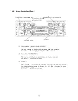
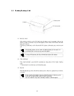
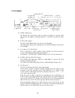
(4) BATTERY BACKUP LED (orange)
With no power supplies for array controller supplying power normally in such a case
as power interruption, the BAT LED lights orange if the cache is subject to battery
backup.
If any of the controllers, power supplies, and batteries is replaced during
the BAT LED ON with no power supplies for array controller supplying
power normally, the backup data is lost.
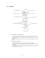
(5) BBU READY LED (green)
The BBU READY LED lights green when the conditions for using the write cache
feature are already provided (see Section 2.2 "Write Cache Feature").
(6) ACCESS LED (green)
The ACCESS LED lights while the controller is operating in the disk array unit.
(7) READY LED (green)
The READY LED lights green while the controller operates normally.
The LED flashes during the self-test or initialization just after power-on.
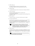
(8) RS-232C
connector
The RS-232C connector is provided for maintenance inspection of the disk array
unit.
This connector is not used normally because it is exclusively used for maintenance.
(9) DE-DIAG
connector
The DE-DIAG connector is provided to connect a cable for diagnosing the disk
enclosure.
Connect the DE diagnosis cable.
(10) DIAG READY LED (green)
The DIAG READY LED lights green when the disk enclosure becomes ready for
diagnosis.
(11) DISK-2G LED (green)
The DISK-2G LED lights green while the disk interface is operating at 2Gbps. The
LED is off while it is operating at 1Gbps.
(12) FC connectors (for connection of disk enclosure) (DEF0/DEF1)
The FC connectors are used to connect the array controller with the disk enclosure.
See Chapter 5 "CONNECTION OF DISK ARRAY UNIT" for the cable connection.
Summary of Contents for NF2300-SR412E
Page 7: ...v ...
Page 8: ...vi ...
Page 9: ...vii ...
Page 10: ...viii ...
Page 63: ...45 ...
Page 65: ...47 Sample configuration 2 NF2300 SR4xxE NF2300 SP02E ...

