iii
CAUTION
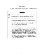
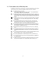
Do not install the disk array unit and the host systems on unstable places. If so,
some substances may be dropped to cause you to be injured.
Do not install the disk array unit and the power cords in an area with direct sunshine
or near an apparatus generating heat such as a heater. If so, a fault may occur.
Further, the coating of the power cord may be melted to cause fire or electric shock
to occur.
Insert the plug of a power cord to an AC outlet securely. Any power cord shall be
routed with sufficient margin to avoid excess force from being given to the plugs of
the power cord or the power cord itself. If a power cord is removed from the AC
outlet during operation, data may be lost and/or a fault may occur.
To prevent electric shocks, connect a power cord to an AC outlet with earth
terminal. Connection of the earth line to a gas tube is extremely dangerous. Never
do it.
Connect or remove a peripheral device from the disk array unit after turning off all
the powers of the disk array unit and peripherals and pulling out the power cords
from the AC outlets. If not, some units may be broken and/or you may be electrically
shocked.
To carry or reinstall the disk array unit, disconnect all cables and power cords
beforehand. If not, some units may be broken, you may be electrically shocked,
and/or a fire may occur.
Handle optical fibers carefully and gently.
The minimum bending radius of optical fiber shall be 30 mm.
Dust and/or dirt may attenuate the optical power of optical fiber to cause data errors
to occur. Clean any optical fiber cable whenever it is inserted into the mating
connector in the following procedure.
1. Blow parts cleaning gas (e.g. air splay) to the connector of the optical fiber cable
for several seconds.
2. Wipe the connector with non-woven cloth soaked with alcohol for several times.
3. Blow the parts cleaning gas to the connector again.
To install the unit in a rack, observe the following guidelines.
1. TMRA – If installed in a rack, consideration should be given to installing the
equipment in an environment compatible with the TMRA.
2. Reduced Air Flow – Installation in a rack should be such that the amount of air flow
required for safe operation of the equipment is not compromised.
3. Mechanical loading – Mounting of the equipment in the rack should be such that a
hazardous condition is not achieved due to uneven mechanical loading.
4. Circuit Overloading – Consideration should be given to the connection of the
equipment to the supply circuit and the effect that overloading the circuits might
have on overcurrent protection and supply wiring. Appropriate consideration of
equipment nameplate ratings should be used when addressing this concern.
5. Reliable Earthing – Reliable earthing of rack-mounted equipment should be
maintained. Particular attention should be given to supply connections other than
direct connections to the branch circuit (e.g., use of power strips).
Summary of Contents for NF2300-SR412E
Page 7: ...v ...
Page 8: ...vi ...
Page 9: ...vii ...
Page 10: ...viii ...
Page 63: ...45 ...
Page 65: ...47 Sample configuration 2 NF2300 SR4xxE NF2300 SP02E ...


