20
3.5 Controller
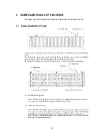
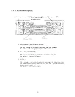
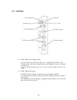
(1) Controller cooling fans (FAN0/FAN1)
With the power switch being ON, the two cooling fans are rotating. Note that the
ventilating holes may not be blocked.
Install the array controller so that the ventilating holes may not be
blocked. If either or both of the ventilating holes are blocked, the
internal temperature of the array controller may increase to cause a
fault to occur.
The controller is equipped with 4 fans in total. Even if a fan fails, the
air-cooling conditions for the entire array controller are satisfied.
However, to guarantee the safety operation of the disk array unit,
replace the controller cooling fan immediately if a fan failure occurs.
(2) FAN LED (FAN0/FAN1) (orange)
The FAN LED lights orange if the cooling fan for the respective controller is not
installed or a fault occurs in the fan. The LED is off while the respective fan operates
normally.
(3) FAULT LED (orange)
The FAULT LED lights orange if a fault occurs in the controller.
(1) Controller cooling fan (FAN1)
(1) Controller cooling fan (FAN0)
(13) FC connector (for connection of
host bus adapter) (HF0)
(15) HOST-2G LED
(14) LINKUP LED
(DL0/DL1)
(8) RS232C connector
(2) FAN LED (FAN0)
(16) AL-PA switch
(14) LINKUP LED (HL0)
(12) FC connectors (for connection of
disk enclosure) (DEF0/DEF1)
(10) DIAG READY LED
(11) DISK-2G LED
(9) DE-DIAG connector
(17) Ejector
(5) BBU READY LED
(2) FAN LED (FAN1)
(6) ACCESS LED
(7) READY LED
(4) BATTERY BACKUP LED
(3)
FAULT
LED
Summary of Contents for NF2300-SR412E
Page 7: ...v ...
Page 8: ...vi ...
Page 9: ...vii ...
Page 10: ...viii ...
Page 63: ...45 ...
Page 65: ...47 Sample configuration 2 NF2300 SR4xxE NF2300 SP02E ...

