background image


 83

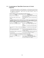
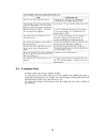
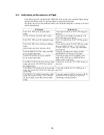
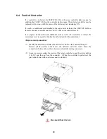
(3)  Turning off AC power 


a)  Turn off the host system or FC-AL switch, and then perform the procedure 

explained in "(2) Notes on AC power-off" before turning off the power. 

 
b)  After finishing the operation in a, turn off the array controller and then all the 

disk enclosures including additional disk enclosures.  Alternatively, turn off 
the array controller and all the disk enclosures including additional disk 
enclosures connected with the array controller at the same time. 
 
The disk array unit has the redundant power configuration to prevent the entire 
unit from shutting down due to a single failure.    Therefore, when turning off 
the disk array unit, turn off all the power switches (of the array controller and 
disk enclosures) at the rear of the unit. 
 
Be careful that data may be lost if you turn off the disk enclosures before the 
array controller. 
 
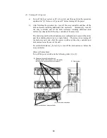
[Power-off procedure] 
Turn off the power switches in the following order (1) to (5): 


(5) Power switches of disk enclosures 

(May be turned off at the same time the power 
switches of array controller are turned off.) 

(1) Host system 

(2) (3) Shut down switches 

(4) Power switches of array controller 

Summary of Contents for NF2300-SR412E

Page 1: ...to the CAUTION and WARNING statements whenever necessary NEC CONFIDENTIAL AND PROPRIETARY All rights reserved by NEC Corporation This document must be used solely for the purpose for which it was furnished by NEC Corporation No part of this document may be reproduced or disclosed to others in any form without the prior written permission of NEC Corporation 856 850305 101 A ...

Page 2: ...nvironment This equipment generates uses and can radiate radio frequency energy and if not installed and used in accordance with the instruction manual may cause harmful interference to radio communications Operation of this equipment in a residential area is likely to cause harmful interference in which case the user will be required to correct the interference at his own expense Warning This is ...

Page 3: ...ere is a risk of death or serious wound CAUTION Indicate there is a risk of burn or injury Risks and necessary actions to reduce risks are indicated individually by the following symbols Indicates the risk of smoke emission or fire outbreak Indicates the risk of electric shock Indicates the danger of an injury due to harmful material Indicates instructions to keep a device away from inflammable ob...

Page 4: ...any If dust remains adhering to an AC outlet and or plug fire may occur Do not connect the plug of a power cord to an AC outlet with a wet hand If so you may be electrically shocked While the disk array unit can accept the power of 100 240 VAC 50 60 Hz the power cord coming with the disk array unit can only accept 100 120 VAC Use 100 120 VAC 50 60 Hz when the attached power cord is used Using powe...

Page 5: ...carefully and gently The minimum bending radius of optical fiber shall be 30 mm Dust and or dirt may attenuate the optical power of optical fiber to cause data errors to occur Clean any optical fiber cable whenever it is inserted into the mating connector in the following procedure 1 Blow parts cleaning gas e g air splay to the connector of the optical fiber cable for several seconds 2 Wipe the co...

Page 6: ...it They are intended to always make you conscious of possible dangers when you handle the disk array unit Do not peel off the labels or do not make them dirty If any of the labels is not put on the proper position is peeled off a little or is dirty to make it unreadable contact your sales agent or maintenance engineer ...

Page 7: ...v ...

Page 8: ...vi ...

Page 9: ...vii ...

Page 10: ...viii ...

Page 11: ...efforts are being made to create this manual but in the event that any technical or editorial errors or omissions are found contact your dealer 4 Save this manual in a convenient area even after you finished reading it 5 When transferring this unit to other person be sure to transfer this manual also 6 NEC shall not be liable for any loss or lost profits from the use of this disk array unit regard...

Page 12: ...OS NEC Storage BaseProduct needs to be purchased separately for using the disk array unit The following options are provided for NF2300 SR4xxE disk array unit To expand storage capacity Additional disk enclosure NF2300 SE41E Additional 36 GB disk drive NF2300 SM412E Additional 73 GB disk drive NF2300 SM413E Additional 147 GB disk drive NF2300 SM414E Additional 36 GB 15 000 rpm disk drive NF2300 SM...

Page 13: ...any of the components is missed contact your sales agent Next inspect the disk array unit and accessories If any of the components is damaged contact your sales agent No Product name Remarks Qty 1 NEC Storage S2300 1 2 1 2 NEC Storage S2300 2 2 1 NF2300 SR412E 36 GB 3 NF2300 SR413E 73 GB 3 NF2300 SR414E 147 GB 3 3 Disk drive Installed in NEC Storage S2300 2 2 NF2300 SR422E 36 GB 15K 3 4 Power cord...

Page 14: ...ith the front mask installed 2 NEC Storage S2300 2 2 The figure above shows the unit with the front mask installed 3 Disk drive 4 Power cord 5 HSSDC cable 6 DE diagnosis cable 7 Front mask 8 Key 9 User s Guide 10 Packing list 11 Location label 12 T D program 13 Rack mount kit ...

Page 15: ... This User s Guide also uses the following symbol Symbol Description Supplement of the text This User s Guide uses the following terms to indicate specific devices Disk array unit Indicates NF2300 SR4xxE Array controller Indicates the NEC Storage S2300 1 2 Disk enclosure Indicates the NEC Storage S2300 2 2 and additional disk enclosure sold separately Disk drive Indicates the hard disk with dedica...

Page 16: ...Management Software 12 2 5 RAID Configuration 13 3 NAMES AND ROLES OF SECTIONS 14 3 1 Array Controller Front 14 3 2 Array Controller Rear 16 3 3 Battery Backup Unit 17 3 4 Power Supply for Array Controller 18 3 5 Controller 20 3 6 LAN Card 23 3 7 Disk Enclosure Front 25 3 8 Disk Enclosure Rear 27 3 9 Power Supply for Disk Enclosure 28 3 10 Adapter 30 3 11 Additional Control Card 32 3 12 Additional...

Page 17: ... of Controller 89 8 5 Fault of Controller Cooling Fan 92 8 6 Fault of LAN Card 93 8 7 Fault of Power Supply for Array Controller 94 8 8 Fault of Battery Backup Unit 97 8 9 Fault of Disk Drive 99 8 10 Fault of Power Supply for Disk Enclosure 102 8 11 Fault of Adapter 106 8 12 Check of Type Name and Manufacturing Numbers 109 8 13 Preparation before Phone Call 111 8 14 Service and Support 111 8 15 Un...

Page 18: ...cal Disk Capacity 128 11 1 Arbitrary Logical Disk Capacity 128 11 2 Maximum Logical Disk Capacity 128 12 Access Control 130 12 1 Port Mode 130 12 2 WWn Mode 130 13 Dynamic Data Replication 131 14 Miscellaneous Settings 131 15 Various Default Values 131 16 Notes on Use of NEC Storage DynamicDataReplication 132 17 Disk Enclosure Movement 133 18 Setting of OS Type 133 19 Program Products 134 20 Updat...

Page 19: ...N INSTALLATION AND HANDLING OF DISK ARRAY UNIT 1 1 Note on Carrying Disk Array Unit Be sure to hold the bottom the disk array unit when carrying it Hold the front or side bottom of the disk array unit if possible ...

Page 20: ...rea suffering liquid such as water and oil suffering steam area with steam and area with much moisture If so a fault or electrical shock may occur Do not install the disk array unit in an area with emission of chemical steam or an area where the disk array unit may be contact with inflammable substance If so a fault fire or explosion may occur Do not install the disk array unit in an area with muc...

Page 21: ...e broken fire may occur and or you may be electrically shocked Do not connect the plug of a power cord to an AC outlet with a wet hand If so you may be electrically shocked CAUTION Make sure to disconnect all power cords and FC cables before relocating the disk array unit If not a malfunction of the system an electric shock and or fire may occur While the disk array unit can accept the power of 10...

Page 22: ...nit so that legs may not be trapped by the cables Avoid power plugs and FC connectors from suffering excess forces Do not use cables connected to the disk array unit with them leaving bent If so a fault or fire may occur Use the cables approved by NEC as those connected to the disk array unit and check the destinations to which the cables are connected In addition always lock power cords and FC ca...

Page 23: ... remain to cause the unit to be defected Do not enter foreign substances such as clip and screw into the disk array unit through the ventilating holes on the front or rear face If so a fault may occur Do not disassemble or modify the disk array unit If so a fault or electrical shock may occur Repair of the unit will be charged regardless of warranty If the disk array unit will not be used for a lo...

Page 24: ...In addition note that splaying insecticide on a surface may cause the surface to be deformed or discolored It is recommended to clean the inside of the disk array unit periodically It is because dust may be accumulated after the disk array unit is used for a long time Contact your sales agent or maintenance engineer for the cleaning of the inside of the disk array unit Users must not disassemble a...

Page 25: ...y unit after storage for longer than six months it is recommended to contact your sales agent or maintenance engineer for inspection and or repair The array controller and the disk enclosure weigh 34 kg or more Hold the array controller and disk enclosure firmly with at least three people to carry it Carrying the devices only by two or less people may strain their back Do not hold the protrusions ...

Page 26: ... the defected disk drive If a single disk drive is specified as the spare disk the data in the defected disk drive can be immediately recovered in the spare disk The use of this hot spare feature as well as the auto repair feature allows the data in the defected disk drive to be automatically recovered in the spare disk as soon as a disk drive is defected This improves the system reliability The d...

Page 27: ...rmal disk drive the data is immediately repaired from the spare disk to the normal disk drive Example of hot spare operation DRV14 Spare disk DRV14 DRV14 Spare disk DRV13 DRV13 DRV13 DRV12 DRV12 DRV12 DRV11 DRV11 DRV11 DRV10 DRV10 DRV10 DRV9 DRV9 DRV9 DRV8 DRV8 DRV8 DRV7 DRV7 DRV7 DRV6 DRV6 DRV6 DRV5 DRV5 DRV5 DRV4 DRV4 DRV4 DRV3 DRV3 DRV3 DRV2 LDN0 RAID5 DRV2 LDN0 RAID5 DRV2 LDN0 RAID5 DRV1 DRV1 ...

Page 28: ...failing disk Therefore if a large capacity disk is defined as a spare disk it can cover all the disks of a high speed drive However if your disk array unit contains disks of different capacities or different rotational speeds you should define a spare disk matching the capacity and rotational speed of each disk in order to clarify disk management Up to 2 spare disks can be installed for each disk ...

Page 29: ... disk drive the data in the cache memory will be lost To prevent this the disk array unit provides the battery backup by power supply and battery backup unit to retain data in the cache memory The backup time is restricted as follows Four days in full charge status of both the two batteries in the installation of cache memory of the maximum capacity The following conditions are imposed to make the...

Page 30: ...nit management software NEC Storage Manager of NEC Storage BaseProduct Ver 2 1 NEC Storage S2300 separately priced that is used with the disk array unit NEC Storage Manager also enables you to set the following parameters through the host computer Setting of RAID configuration RAID0 1 5 10 and hot spare disk Resetting of RAID configuration Setting of various features such as cross call mode Collec...

Page 31: ...onfiguring logical drives The RAID levels have the following characteristics Level Function Advantage Disadvantage RAID0 Striping Highest data read write rate Maximum storage capacity Data recovery disabled Fault in a single disk drive causes data to be lost RAID1 Mirroring Data recovery enabled Low speed data writing All data is written to two disk drives Minimum data recovery time The storage ca...

Page 32: ...e figure below 1 POWER LED green The POWER LED lights green if the AC power is supplied and the power switch is set to ON The LED is off if the power switch is set to OFF 2 SERVICE LED orange The SERVICE LED lights orange when the disk array unit encounters an error and it is also on while the battery backup unit is being charged The LED flashes during the self test and initialization immediately ...

Page 33: ...battery backup units installed in the disk array unit 4 Battery backup units BBU0 BBU1 The battery backup units are installed to protect the data remaining in the cache memory at the occurrence of power interruption See Section 3 3 Battery Backup Unit for details ...

Page 34: ...ntroller boards are provided to control the disk array unit See Section 3 5 Controller for details 3 LAN card The LAN card is used to write the cache data remaining in the disk array unit into the disk drive before turning off the unit The LAN card is provided for remote maintenance of the unit See Section 3 6 LAN Card for details 1 Power supply for array controller PS1 1 Power supply for array co...

Page 35: ... at the occurrence of power interruption Turning off the battery backup unit disables write cache feature 2 Check terminal The check terminal is provided for maintenance inspection of the battery backup unit This terminal is exclusively used for maintenance 3 Handle Hold the handle to pull out the battery backup unit when it is replaced due to failure or its life When inserting the battery backup ...

Page 36: ...the power of 100 240 VAC 50 60 Hz the power cord coming with the disk array unit can only accept 100 120 VAC Use 100 120 VAC 50 60 Hz when the attached power cord is used Using power of different voltage may cause electric shock smoke and or fire to occur 2 Power switch The power switch is used to turn on off the power of the array controller The array controller has the redundant power configurat...

Page 37: ...en the AC power is supplied to the array controller and the power switch is set to ON The LED is off if the power switch is set to OFF or a fault occurs in the power supply 5 POWER FAIL LED orange The POWER FAIL LED lights if a fault occurs in the power supply 6 BBU FAIL LED orange The BBU FAIL LED lights when the respective battery backup unit is installed and a fault occurs in the battery backup...

Page 38: ...it replace the controller cooling fan immediately if a fan failure occurs 2 FAN LED FAN0 FAN1 orange The FAN LED lights orange if the cooling fan for the respective controller is not installed or a fault occurs in the fan The LED is off while the respective fan operates normally 3 FAULT LED orange The FAULT LED lights orange if a fault occurs in the controller 1 Controller cooling fan FAN1 1 Contr...

Page 39: ...le the controller operates normally The LED flashes during the self test or initialization just after power on 8 RS 232C connector The RS 232C connector is provided for maintenance inspection of the disk array unit This connector is not used normally because it is exclusively used for maintenance 9 DE DIAG connector The DE DIAG connector is provided to connect a cable for diagnosing the disk enclo...

Page 40: ...green while the host bus adapter interface is operating at 2Gbps The LED is off while it is operating at 1Gbps 16 AL PA switch The AL PA switch is used to set the address of the disk array unit as a FibreChannel device in the host FC loop At the shipment the addresses of CONT0 and CONT1 are set to 00 and 01 respectively Set the AL PA so that the address may not be the same as that of another contr...

Page 41: ... Power On Off of Disk Array Unit for details 2 SHUT DOWN LED green The SHUT DOWN LED goes off while the LAN card operates normally The LED flashes green while writing the cache data remaining in array controller to the disk drive The LED lights when the cache data is completely written to disk drive and the disk array unit is ready to power off 4 LINK LED 5 FAULT LED 6 RS232C connector 8 Ethernet ...

Page 42: ...ower from the UPS If the system configuration using the UPS is implemented the system can continue operating in stable state even if an unexpected power failure or momentary AC power failure occurs Ask your sales agent for the system configuration using the UPS If you want to change the current system connection contact your maintenance service agent If you change the connection by yourself the UP...

Page 43: ... front mask you can view the disk drive shown in the figure below 1 POWER LED green The POWER LED lights green if the AC power is supplied and the power switch is set to ON The LED is off if the power switch is set to OFF 2 SERVICE LED orange The SERVICE LED lights orange if an error occurs in the disk enclosure The LED is off while the disk enclosure operates normally 1 POWER LED 2 SERVICE LED 2 ...

Page 44: ...closure 4 HDD READY LED green The HDD READY LED lights green while the disk drive operates normally The LED flashes when the disk drive transfers data The HDD READY LED flashes during the self test or initialization just after power on 5 HDD FAULT LED orange The HDD FAULT LED lights at the occurrence of an error in the disk drive The LED is off while the disk drive operates normally 6 Ejector The ...

Page 45: ...upply failure or adapter failure again When replacing a power supply for the disk enclosure prepare the new power supply before removing the old one and then replace it within about 3 minutes The following are heating units of the disk enclosure A Disk drives B Power supplies for the disk enclosure The fans in the power supplies for the disk enclosure serve as cooling fans for both of the above Th...

Page 46: ...closure has the redundant power configuration to prevent the entire disk array unit from shutting down due to a single failure Therefore turn on off the two power switches when operating the disk enclosure 3 Cooling fans When the power switch is set to ON two cooling fans are rotating Note that the ventilating holes are not blocked Install the disk enclosure so that the ventilating holes may not b...

Page 47: ...sk enclosure Loosen the screw before using the ejector When inserting the power supply for the disk enclosure into the disk enclosure push it as far as it will go and then secure it with the screws Incorrect insertion may cause a power supply failure again When replacing a power supply for the disk enclosure prepare the new power supply before removing the old one and then replace it within about ...

Page 48: ...tch The AL PA switch sets the AL PA of the disk enclosure Set the AL PA switches of both the adapters installed in the first disk enclosure connected to the array controller via FC cable HSSDC to 0 Further set the AL PA switches of the adapters installed in each disk enclosure to 1 2 5 or 6 in the connection order When the AL PA switches of the left and right adapters are set differently the FAULT...

Page 49: ...er 1 ADP1 To connect the additional disk enclosure NF2300 SE41E to the disk array unit make the following connections From the PORT1 connector of adapter 0 ADP0 installed in the disk enclosure of the disk array unit to the PORT0 connector of adapter 0 ADP0 installed in the additional disk enclosure From the PORT1 connector of adapter 1 ADP1 installed in the disk enclosure of the disk array unit to...

Page 50: ... FC port becomes operable Link UP DL2 LED corresponds to the DEF2 connector DL3 LED corresponds to the DEF3 connector and HL1 LED corresponds to the HF1 connector The LED is off during the self test or initialization just after power on 4 DISK 2G LED green The DISK 2G LED lights green while the disk interface is operating at 2Gbps The LED is off while it is operating at 1Gbps 5 HOST 2G LED green T...

Page 51: ...ling or replacing the additional control card into the controller push it as far as it will go and then secure it with the screws Incorrect insertion may cause malfunction To use the additional control card at least a single cache memory must be installed NF2300 SP02E does not contain cache memory Purchase the necessary additional cache memory NF2300 SC01E or NF2300 SC02E depending on the environm...

Page 52: ...n The HOST 2G LED lights green while the host bus adapter interface is operating at 2Gbps The LED is off while it is operating at 1Gbps 4 AL PA switch The AL PA switch sets the address of the disk array unit as a FibreChannel device in the host FC loop Set an AL PA so that it will be different from the AL PAs of other FibreChannel devices in the same host FC loop When installing or replacing the a...

Page 53: ...he package following Check of Components in Package If any component is missed contact your sales agent Connection of host bus adapter Connect the host bus adapter according to the manual provided with the host system or host bus adapter And install the proper driver Connection of FC cable Use the cable compatible with the disk array unit Insert the connector until the latch emits a click Do not b...

Page 54: ...cted to the proper destinations based on the cable specification Do not push any cable connector excessively Each connector can be connected properly only when it is inserted to the mating connector in the correct direction and at the correct angle Proper insertion allows the connector to be inserted to the mating connector smoothly without excess force If the connector cannot be inserted smoothly...

Page 55: ...nclosure or the NEC specified DE cable NF9120 SJ04E 2 Cable length limit FC optical cable for operating the host interface at 1Gbps Up to 500 m FC optical cable for operating the host interface at 2Gbps Up to 300 m 3 Settings of topology and data transfer rate A topology and data transfer rate must be set correctly in accordance with the host bus adapter to be connected or the connection mode of t...

Page 56: ...with the host system Two LC LC cables or two SC SC cables and two FC conversion cables are necessary for connecting the host bus adapters a With the host bus adapter connectors of LC type The second and following disk enclosures are optional See Section 6 2 Addition of Disk Enclosure HSSDC cables DE diagnosis cables FC cables LC LC cables HSSDC cables DE diagnosis cables ...

Page 57: ...sk enclosures are optional See Section 6 2 Addition of Disk Enclosure Connect the disk array unit with the host unit by using an FC cable in the following procedure HSSDC cables DE diagnosis cables HSSDC cables DE diagnosis cables SC SC cables Relay connectors FC conversion cables ...

Page 58: ... that the power switch on the disk array unit and those on the host system are set to OFF and the plugs of the power cords are removed from AC outlets a Power supply for array controller OFF ON b Power supply for disk enclosure OFF ON ...

Page 59: ...s adapter connectors of SC type Use the separately priced FC conversion cable NF9310 SJ10E The cable has different size connectors at the ends Push the smaller connector into the FC connector HFx for the host bus adapter of either controller CONT0 or CONT1 until a click is heard If the connector is pushed hard the end face may be hurt to decrease optical output This may cause invalid operation to ...

Page 60: ...pter 0 ADP0 of the disk enclosure until a click is heard Similarly connect the DE DIAG connector of the other controller 1 CONT1 to the DE DIAG connector PORT0 on adapter 1 ADP1 of the disk enclosure If you have installed the additional control card NF2300 SP02E in the NF2300 SR4xxE push the connector at either end of the FC cable HSSDC into the FC connector DEF2 for the disk enclosure on addition...

Page 61: ...ost FC loop The corresponding table between the AL PA switch and AL PA is shown on the next page b Setting of AL PA switch on disk enclosure Set the AL PA by using the AL PA switch on each adapter Set the AL PA so that it may not be the same as that of another disk enclosure on the same FC loop Set the AL PA switches of both the adapters installed in the first disk enclosure connected to the array...

Page 62: ...0 E1 04 AD 23 6E 42 39 61 E0 05 AC 24 6D 43 36 62 DC 06 AB 25 6C 44 35 63 DA 07 AA 26 6B 45 34 64 D9 08 A9 27 6A 46 33 65 D6 09 A7 28 69 47 32 66 D5 0A A6 29 67 48 31 67 D4 0B A5 2A 66 49 2E 68 D3 0C A3 2B 65 4A 2D 69 D2 0D 9F 2C 63 4B 2C 6A D1 0E 9E 2D 5C 4C 2B 6B CE 0F 9D 2E 5A 4D 2A 6C CD 10 9B 2F 59 4E 29 6D CC 11 98 30 56 4F 27 6E CB 12 97 31 55 50 26 6F CA 13 90 32 54 51 25 70 C9 14 8F 33 53...

Page 63: ...45 ...

Page 64: ...46 Outline of cable connections on disk enclosures and settings of AL PA DE DIAG switches Sample configuration 1 NF2300 SR4xxE ...

Page 65: ...47 Sample configuration 2 NF2300 SR4xxE NF2300 SP02E ...

Page 66: ...configuration contact your service engineer of the maintenance service agent with expert knowledge on the disk array unit To make any of the sample connections you need to connect two host bus adapters with the host system and two FC AL HUBs Six LC LC cables or six SC SC cables and four FC conversion cables are necessary for connecting the FC AL HUB and host bus adapters a If the host bus adapter ...

Page 67: ...it by using an FC cable in the following procedure 1 Power check Make sure that the power switch of the disk array unit and that of the host unit are set to OFF and the plugs of the power cords are removed from AC outlets FC AL HUB FC conversion cable and SC SC cable SC SC cables FC AL HUB FC conversion cable and SC SC cable ...

Page 68: ...sively may injure the tip to decrease the optical intensity which will then cause malfunction to occur Similarly connect the controller on the other array controller board to the FC AL HUB Connect the connector at one end of the FC cable to the connector for connecting the host bus adapter installed in the host system and the connector at the other end to the above FC AL HUB Be sure to push the co...

Page 69: ...er on the other array controller board to the FC AL HUB Connect the connector at one end of the SC SC cable to the connector for connecting the host bus adapter installed in the host system and the connector at the other end to the above FC AL HUB Be sure to push the connectors until a click is heard Subsequently connect the FC connector HFx for the host bus adapter which is at the controller on e...

Page 70: ...tion of Ethernet cable Connect the separately priced Ethernet cable to the LAN modular jack on the LAN card Connect the host system on which the management software NEC Storage Manager is installed to Ethernet Only connecting the cable to the LAN card cannot make it possible to use the NEC Storage Manager through Ethernet Contact your service engineer of the maintenance service agent with expert k...

Page 71: ...ds provided with the disk array unit or NEC specified power cords The disk array unit has the redundant power configuration to prevent the entire unit from shutting down due to a single failure Therefore connect two power cords to both the array controller and the disk enclosure when operating the disk array unit Connect the power cords in the following procedure 1 Check of power supply Check that...

Page 72: ...r supply of the array controller is placed outward as shown in the figure below Then inset the power cord to the plug When connecting the power supply of the disk enclosure push down the power cord stopper for the power cord toward the left insert the power cord and then secure the power cord by firmly fitting the power cord stopper into the receptacle of the power cord ...

Page 73: ...minal for the connection as shown in the figure below While the disk array unit can accept the power of 100 240 VAC 50 60 Hz the power cord coming with the disk array unit can only accept 100 120 VAC Use 100 120 VAC 50 60 Hz when the attached power cord is used Using power of different voltage may cause electric shock smoke and or fire to occur ...

Page 74: ...300 SR422E 36 GB disk drives 15 000 rpm The disk enclosure can be equipped with up to 15 disk drives Product name Part number Capacity Additional disk drive NF2300 SM412E 36GB 10 000 rpm Additional disk drive NF2300 SM413E 73GB 10 000 rpm Additional disk drive NF2300 SM414E 147GB 10 000 rpm Additional disk drive NF2300 SM422E 36GB 15 000 rpm If an additional disk drive and standard disk drive are ...

Page 75: ...e a spare disk matching the capacity and rotational speed of each disk in order to clarify disk management Up to 2 spare disks can be installed for each disk enclosure Up to 16 spare disks can be installed for the entire disk array unit Installation procedure Disk drives may be installed in the disk enclosure with the powers of the disk array unit and host unit being ON For the replacement of two ...

Page 76: ...out the dummy tray Be sure to keep removed dummy trays in the designated place After removing an additional disk drive from the unit be sure to install a dummy tray into the slot If using the unit without a dummy tray being installed cooling effect on the disk drives lowers and causes heat generation Heat generation increases the failure rate and at its worst it may cause data loss ...

Page 77: ...ejector opened upward to click for locking When inserting the disk drive into the disk enclosure push it as far as it will go and then lock the ejector Incorrect insertion may cause malfunction The disk array unit cannot use the disk drive only if the disk drive is installed additionally Provide the proper setting for the disk drive by using the NEC Storage Manager feature of the disk array unit o...

Page 78: ...F2300 SM412E is additionally installed in NF2300 SR412E write down check marks at the locations in which the disk drives are installed which appears in the area to the right of the model number field If the model number of disk drive additionally installed does not appear in the model number field enter the last two digits of model number in NF2300 SM4 E field Write down a check mark at the locati...

Page 79: ...ty adding one or more disk enclosures allows disk drives to be added Up to 105 disk drives may be installed with up to six additional disk enclosures With the installation of additional control card NF2300 SP02E up to 13 additional disk enclosures and up to 210 disk drives may be installed Product name Additional disk enclosure Part number NF2300 SE41E Be sure to install disk drives into PD00 and ...

Page 80: ...the FC IN connector on adapter 0 ADP0 of the additional disk enclosure until a click is heard Similarly connect the FC OUT connector on adapter 1 ADP1 of the existing disk enclosure to the FC IN connector on adapter 1 ADP1 of the additional disk enclosure Subsequently use the DE diagnosis cable provided with the additional disk enclosure or the DE diagnosis cable of the separately priced DE cable ...

Page 81: ...the FC IN connector on adapter 1 ADP1 of the additional disk enclosure Do not connect any cable connector to the DEF3 connector of additional control card on controller 0 CONT0 or DEF2 connector of the additional control card on controller 1 CONT1 Subsequently use the DE diagnosis cable provided with the additional disk enclosure or the DE diagnosis cable of the separately priced DE cable NF9120 S...

Page 82: ...n each adapter flashes and the disk enclosure fails to start If you have set different values turn off the system including the additional disk enclosure set the same value for the AL PA switches and then turn on the power b Setting of DE DIAG ID switch on disk enclosure Set a DE DIAG ID by using the DE DIAG ID switch on each adapter of the additional disk enclosure Set 0 for all the DE DIAG IDs o...

Page 83: ...itional disk enclosure into the power plug on the power supply of the disk enclosure You can use the NEC specified power cord alternatively When connecting the power supply of the disk enclosure push down the power cord stopper for the power cord toward the left insert the power cord and then secure the power cord by firmly fitting the power cord stopper into the receptacle of the power cord ...

Page 84: ...power of 100 240 VAC 50 60 Hz the power cord coming with the disk array unit can only accept 100 120 VAC Use 100 120 VAC 50 60 Hz when the attached power cord is used Using power of different voltage may cause electric shock smoke and or fire to occur The disk array unit cannot use the disk enclosure only if the disk enclosure is installed additionally Provide the proper setting for the disk enclo...

Page 85: ... hit on some object when your hands are entered into the disk array unit Do not disassemble or modify the additional control card Failure to follow it may cause the unit to be defected The disk array unit can be normally connected with up to six additional disk enclosures For larger capacity installing an additional control card allows disk enclosures to be added further Up to 13 additional disk e...

Page 86: ... the host bus adapter by operating the DIP switch SW1 on the additional control card For details see Section 9 7 How to Change Topology and Data Transfer Rate Factory set topology and data transfer rate Topology FC AL Data transfer rate 2Gbps 3 Removal of cables Remove all the cables connected to the controller Write down the connections between the cables to be removed and the mating connectors 4...

Page 87: ...stall a blank panel into the slot If using the unit without a blank panel being installed cooling effect on the array controller lowers and causes heat generation Heat generation increases the failure rate and at its worst it may cause data loss 6 Installation of additional control card Install an additional control card in the controller With the screw holes as reference place the additional cont...

Page 88: ...ith the screws Incorrect installation may cause malfunction Install the separately purchased additional cache memory into the additional control card Install the required number of additional cache memories into connectors CHE4 to CHE7 according to the following procedure Open the socket levers and install the cache memory fitting the two recesses of the cache memory to the protrusions of the sock...

Page 89: ...he end securely The lock of the protection shutter closed when the controller was pulled out is automatically released by inserting the controller Insert the controller as far as it will go and close the ejector Strongly push the ejector the part indicated by the arrow in the figure until the controller is inserted firmly and secure the ejector with the screw When inserting the controller into the...

Page 90: ... for installation is put to allow the installed options to be known by external view If the additional control card and additional host FC port are added write a round mark at the corresponding field on the label to indicate the addition as shown in the figure below Write a round mark at this field Note The figure above shows the case in which NF2300 SP02E is added If a cache memory is installed o...

Page 91: ...t on some object when your hands are entered into the disk array unit Do not disassemble or modify the additional host FC port Failure to follow it may cause the unit to be defected The disk array unit enables the number of host units connectable to the disk array unit to be increased by adding the additional host FC port Product name Additional host FC port Part number NF2300 SP03E NF2300 SP03E i...

Page 92: ... To use an additional control card or to use larger capacity of cache memory for improving the feature of the disk array unit up to four cache memories can be added for each controller and additional control card Product name Additional 512MB cache memory Part number NF2300 SC01E Product name Additional 1GB cache memory Part number NF2300 SC02E Cache memories with different capacities may coexist ...

Page 93: ...ing in the cache memory of the array controller is lost If BAT LED is on perform the procedure explained in Section 7 2 2 Notes on turning off AC power not to leave any unwritten data in the cache memory of the array controller After that turn off the power switch of the disk array unit and then add new cache memory 2 Removal of cables Remove all the cables connected to the controllers Write down ...

Page 94: ...recesses of the cache memory to the protrusions of the socket Confirm that they are fit correctly Until the cache memory is secured by the levers push the cache memory along the connector rail as far as it will go Be careful not to apply excess force to the cache memory in doing so The levers fit into the notches of the cache memory and secure it When installing the additional cache memory to the ...

Page 95: ...ly released by inserting the controller Insert the controller as far as it will go and close the ejector Strongly push the ejector the part indicated by the arrow in the figure until the controller is inserted firmly and secure the ejector with the screw When inserting the controller into the array controller push it as far as it will go and then secure it with the screws Incorrect insertion may c...

Page 96: ...options available for installation is put to allow the installed options to be known by external view If the additional cache memory is added write a round mark at the corresponding field on the label to indicate the addition as shown in the figure below Write round mark as shown in the figure Note The figure above indicates the addition of a single NF2300 SC01E If a single NF2300 SC02E is added w...

Page 97: ...ndicated on the host system do not give vibrations and shocks to the disk array unit Because the disk array unit is a precision device it shall not be subject to hard vibration or shock The features of the disk array unit are effective only for the hardware failure e g the hard disk is physically damaged or inoperative The software failure e g the data is lost or rewritten due to program excursion...

Page 98: ...turn on all the power switches of the array controller and disk enclosures at the rear of the unit When turning on the power switches confirm that the POWER GOOD LED green of the power supply and the POWER LED green on the front panel of the unit go on Power supply starts and the POWER LED green is on while the power switches are on The disk array unit performs the self test and initialization imm...

Page 99: ...taReplication is used execute the Unpair command 3 Turn on the shut down switch toggle switch with SHUT DOWN indicated of the LAN card in the array controller 1 4 Confirm that SDN LED of the LAN card in the array controller is on and then turn off the AC power according to the procedure explained in 3 Turning off AC power SDN LED flashes while remaining data is being written from the cache memory ...

Page 100: ...the AC power after SDN LED goes on BAT LED goes on in the following case NEC Storage DynamicDataReplication is used but you attempt to write the remaining cache data before executing the Unpair command In the above case turn on the AC power of the entire disk array unit again When the disk array unit has started when the READY LED of the controller on the array controller stops flashing and enters...

Page 101: ...ame time The disk array unit has the redundant power configuration to prevent the entire unit from shutting down due to a single failure Therefore when turning off the disk array unit turn off all the power switches of the array controller and disk enclosures at the rear of the unit Be careful that data may be lost if you turn off the disk enclosures before the array controller Power off procedure...

Page 102: ...r service representative for setting of the spare disk For spare disk make sure to assign the disk drive in slot 14 If slot 14 already contains a disk drive for a spare disk install the additional disk drive in slot 13 When you change a failing disk to a spare disk confirm the following to get the spare disk to function normally The capacity of the spare disk is equal to or greater than that of th...

Page 103: ... the AC outlets Then ask your sales agent or maintenance engineer to inspect and repair the disk array unit immediately Using the disk array unit as it is may cause electric shock or fire to occur The user must never repair the disk array unit because it is dangerous CAUTION Note that your fingers may not be caught or hit on some object when your hands are entered into the disk array unit If a fau...

Page 104: ...or the LOOP STATUS LED green of the host bus adapter connected with the FC cable does not go on Cause Countermeasures The FC cable is not connected correctly Insert the connector of the FC cable until a click is heard See Chapter 5 CONNECTION OF DISK ARRAY UNIT The length of the FC cable exceeds the rating value See Chapter 5 CONNECTION OF DISK ARRAY UNIT The setting of the host bus adapter or tha...

Page 105: ...nit Use the host bus adapter available for the disk array unit Contact your sales agent if unknown The disk array unit is installed in an area in which it easily suffers vibration and or shocks Install the disk array unit referring to Chapter 1 NOTES ON INSTALLATION AND HANDLING OF DISK ARRAY UNIT The power is turned off or the reset button on the host system is pressed with the ACCESS LED green b...

Page 106: ...drive is probably defected Check if another FAULT LED is on Contact your maintenance service agent The POWER FAIL LED on a array controller power supply lights orange The array controller power supply with the POWER FAIL LED being on is defected The BBU FAIL LED on a array controller power supply lights orange The battery backup unit corresponding to the BBU FAIL LED being on BBU0 for PS0 or BBU1 ...

Page 107: ...ll the caches and additional cards as well as the controller or contact the maintenance service agent to identify the defected unit for the replacement Replacement procedure 1 Identify the defected controller with the FAULT LED on the controller being lit Remove all the cables connected to the defected controller Write down the connections between the cables to be removed and the mating connectors...

Page 108: ... the same as that of the defected controller 4 Open the ejectors of the controller for replacement insert the controller into the slot to the end securely The lock of the protection shutter closed when the controller was pulled out is automatically released by inserting the controller ...

Page 109: ...in the figure until the controller is inserted firmly and secure the ejector with the screw When inserting the controller into the array controller push it as far as it will go and then secure it with the screws Incorrect insertion may cause malfunction 5 Connect the cables removed in step 1 to the mating connectors as before ...

Page 110: ...ling fan is FAN0 or FAN1 depending on the FAN LED being on 2 Loosen the two set screws at the upper right and lower left corners of the defected controller cooling fan to pull out it from the slot Note that the fan may be rotated by inertia 3 Insert the controller cooling fan for replacement into the slot 4 Fasten the two set screws at the upper right and lower left corners of the controller cooli...

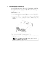
Page 111: ...ed with the power of the disk array unit remaining ON Replacement procedure 1 Loosen a single set screw of the defected LAN card Then pull out the card from the slot You should not disconnect the cables from the defected LAN card when pulling it out 2 Remove all the cables from the defected LAN card and connect them to the LAN card for replacement to the same connectors as the defected LAN card 3 ...

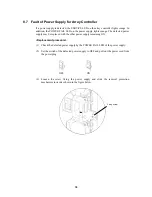
Page 112: ...d power supply may be replaced with the other power supply remaining ON Replacement procedure 1 Check the defected power supply by the POWER FAIL LED of the power supply 2 Set the switch of the defected power supply to OFF and pull out the power cord from the power plug OFF ON 3 Loosen the screw fixing the power supply and slide the removal protection mechanism inward as shown in the figure below ...

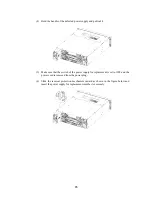
Page 113: ...Make sure that the switch of the power supply for replacement is set to OFF and the power cord is removed from the power plug 6 Slide the removal protection mechanism inward as shown in the figure below and insert the power supply for replacement into the slot securely ...

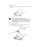
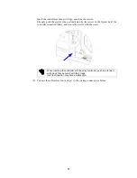
Page 114: ...le screw When inserting the power supply into the array controller push it as far as it will go and then secure it with the screws Incorrect insertion may cause malfunction 8 Connect the power cord of the replaced power supply to the power plug Then set the power switch to ON ...

Page 115: ...ler 2 Loosen the three screws fixing the battery cover of the array controller to remove the cover 3 Set the battery switch of the defected battery backup unit to OFF 4 Loosen the two set screws of the defected battery backup unit and pull out the battery backup unit from the slot Because the battery backup unit has a drop protection claw it cannot be pulled out only by pulling it straight If the ...

Page 116: ...o the notch on the chassis slide the unit to the left and insert it slowly When inserting the battery backup unit into the array controller push it as far as it will go and then secure it with the screws Incorrect insertion may cause malfunction 7 Set the battery switch of the replaced battery backup unit to ON 8 Install the battery cover on the array controller 9 Install the front mask on the arr...

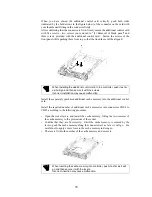
Page 117: ...f the FAULT LED on a disk drive lights replace the disk drive immediately Perform the replacement job as quick as possible Do not operate the disk enclosure for a long time in the state that the disk drive is pulled out Replace the defected disk drive with a disk drive having the same storage capacity Replacement procedure 1 Confirm the defected disk drive with the FAULT LED on the disk drive bein...

Page 118: ... drive opened engage the guides on the top and bottom faces of the disk drive with the guide grooves on the disk enclosure and insert the disk drive to the end slowly After the disk drive is inserted to the end securely push down the ejector opened upward to click for locking When inserting the disk drive into the disk enclosure push it as far as it will go and then lock the ejector Incorrect inse...

Page 119: ...o start recovery Otherwise the reduced state reduce shown as the logical disk status remains Setting the auto pair feature to ON in recovery wait state does not start recovery The setting is enabled starting with the next recovery 6 The disk array unit operates normally during the data recovery At the termination of the data recovery the SERVICE LEDs on the array controller and disk enclosure go o...

Page 120: ...w power supply before removing the old one and then replace it within about 3 minutes The following are heating units of the disk enclosure A Disk drives B Power supplies for the disk enclosure The fans in the power supplies for the disk enclosure serve as cooling fans for both of the above Therefore do not leave the disk enclosure with one of the power supplies removed Doing so causes the disk dr...

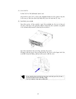
Page 121: ...nd pull it toward you When the ejector turns by 90o pull out the defected power supply When the defected power supply comes out hold it with both hands and slowly remove it 3 Confirm that the power switch of the new power supply for the disk enclosure is off and the power cord is disconnected from the power plug ...

Page 122: ...nd push in the new power supply 6 Strongly push the ejector the part indicated by the arrow in the figure until the new power supply for the disk enclosure is inserted firmly and secure the ejector with the screw When inserting the power supply for the disk enclosure into the disk enclosure push it as far as it will go and then secure it with the screws Incorrect insertion may cause a power supply...

Page 123: ...ply of the disk enclosure push down the power cord stopper toward the left insert the power cord and secure the power cord by firmly fitting the power cord stopper into the receptacle of the power cord After that turn on the power switch ...

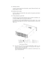
Page 124: ...of the array controller and disk enclosure remaining ON Replacement procedure 1 Confirm the defected adapter with the FAULT LED on the adapter being on Remove all the cables connected to the defected adapter Write down the connections between the cables to be removed and the mating connectors 2 Loosen a screw securing the ejector put your finger on the protrusion shown in the figure of the ejector...

Page 125: ...acement is set to the same value as that of the defected adapter as well as the sound adapter If the adapter is installed with different setting of AL PA switch a link failure may occur in the worst case 5 Insert the adapter for replacement to the slot with the ejector remaining opened until the adapter is carried to the end securely 6 Insert the adapter as far as it will go and close the ejector ...

Page 126: ...pter is inserted firmly and secure the ejector with the screw When inserting the adapter into the disk enclosure push it as far as it will go and then secure it with the screws Incorrect insertion may cause malfunction 8 Connect the cables removed in step 1 to the mating connectors as before ...

Page 127: ... array unit are shown at the locations in the figure below Manufacturing number label of array controller Manufacturing number label of basic enclosure Manufacturing number label of controller Manufacturing number label of battery backup unit Manufacturing number label of power supply for array controller ...

Page 128: ...110 Manufacturing number label of disk enclosure Manufacturing number label of basic enclosure Manufacturing number label of adapter Manufacturing number label of power supply for disk enclosure ...

Page 129: ... service life of the disk array unit may become shorter than 5 years depending on the operating environment Therefore the components should be replaced periodically For their replacement and lives contact your maintenance service agent Service life of the disk array unit 5 years 1 Extended life after overhaul 2 years 2 Repair service period 5 years after stopping of the production Note that the fo...

Page 130: ...M413E Additional disk drive 1 73 GB 10 000 rpm NF2300 SM414E Additional disk drive 1 147 GB 10 000 rpm NF2300 SM422E Additional disk drive 1 36 GB 15 000 rpm NF2300 SC01E Additional 512 MB cache memory 1 For 2 controllers 256MB 2 NF2300 SC02E Additional 1 GB cache memory 1 For 2 controllers 512MB 2 NF2300 SP02E Additional control card 1 For 2 controllers NF2300 SP03E Additional host FC port 1 For ...

Page 131: ...t Array controller Disk enclosure Input voltage 100 to 240 VAC 10 50 60 Hz Maximum power consumption 330 VA 520 VA While the disk array unit can accept the power of 100 240 VAC 50 60 Hz the power cord coming with the disk array unit can only accept 100 120 VAC Use 100 120 VAC 50 60 Hz when the attached power cord is used 9 5 External Dimension and Weight of Disk Array Unit The table below shows th...

Page 132: ...e host bus adapter to be connected the FC AL switch and the connection mode Before attempting to change the settings contact your maintenance service agent Changing the settings needs time for setting and confirming new values You need to provide enough time during which you can stop the system DIP switch of controller If the FC port connector of the controller is placed on the right side use the ...

Page 133: ...nal control card or additional host FC port is placed on the right side use the DIP switch in the rear of the right side Bit position Setting and function 1 Fixed to OFF Reserved 2 Factory set to OFF Topology OFF FC AL ON Fablic 3 Factory set to OFF HOST MODE OFF 2 Gbps ON 1 Gbps 4 to 8 Fixed to OFF Reserved ...

Page 134: ...ng code 6830 Controller Event 3 The disk array unit is started normally by turning the array controller off once and then on again 2 Cross Call Feature The disk array unit contains several features on the cross call 2 1 Initial Assignment Feature 1 The path side controller with a logical disk bound is subject to the assignment of the logical disk If an attempt is made to access to the logical disk...

Page 135: ...Assignment Mode in Guide to Setting of NEC Storage Manager Configuration for the use of the management software NEC Storage Manager 2 3 Cross Call Feature The disk array unit originally has the dynamic cross call feature The feature may be made on or off 1 Default state Off 2 Cross call enable state The cross call feature is set to ON In the state both controllers can access to every logical disk ...

Page 136: ...Windows NT the installation of Service Pack 4 or later and the addition of registries are required Refer to the manual of the Service Pack for the procedure The settings may be done in ports The management software NEC Storage Manager can provide the settings See Several Settings on Disk Array Set of Expand LUN in the Guide to Setting Configuration of NEC Storage Manager for how to use the managem...

Page 137: ... in the 1 BBU status ON Provides operation in the write cache enable mode even in the 1 BBU status default The 1 BBU status means that only a single BBU is installed in the system or the available number of installed BBUs is 1 due to occurrence of a fault To set the mode contact the service engineer with expert knowledge in your sales agent 7 1 Controller Cache Enable Mode If only a single control...

Page 138: ...Do not use the created logical disk as it is After the OS recognizes the logical disk be sure to unbind it by using the management software NEC Storage Manager and then bind it For how to use the management software NEC Storage Manager see Several settings on PD RANK unbind and LD unbind in Guide to Setting of NEC Storage Manager Configuration 10 Dynamic Capacity Expansion The addition of a single...

Page 139: ...ich Veritas volume management software VxVM is used Without the label replacement job only the rank capacity expansion dynamic capacity expansion cannot make the logically expanded capacity recognized Accordingly the capacity logically expanded cannot be used effectively The following describes the label replacement job as well as the jobs around the rank capacity expansion by actual job samples i...

Page 140: ...2000 scsi 1 sd 4 3 5 c3t4d4 NEC NEC Storage2000 W269 cyl 1020 alt 2 hd 16 sec 128 pci 6 2000 scsi 1 sd 4 4 Specify disk enter its number 1 Select target disk selecting c3t4d0 disk formatted FORMAT MENU disk select a disk type select define a disk type partition select define a partition table current describe the current disk format format and analyze the disk repair repair a defective sector labe...

Page 141: ...partition map and label to the disk cmd execute cmd then return quit partition p Select p indicating print check the contents of partition Part Tag Flag Cylinders Size Blocks 0 root wm 0 31 32 00MB 32 0 0 65536 1 swap wu 32 95 64 00MB 64 0 0 131072 2 backup wu 0 1019 1020 00MB 1020 0 0 2088960 3 unassigned wm 0 0 0 0 0 0 4 unassigned wm 0 0 0 0 0 0 5 unassigned wm 96 545 450 00MB 450 0 0 921600 6 ...

Page 142: ...e from the menu AVAILABLE DRIVE TYPES 0 Auto configure 1 Quantum ProDrive 80S 2 Quantum ProDrive 105S 3 CDC Wren IV 94171 344 4 SUN0104 5 SUN0207 6 SUN0327 7 SUN0340 8 SUN0424 9 SUN0535 10 SUN0669 11 SUN1 0G 12 SUN1 05 13 SUN1 3G 14 SUN2 1G 15 SUN2 9G 16 Zip 100 17 Zip 250 18 SUN9 0G 19 NEC NEC Storage2000 W269 20 NEC NEC Storage2000 W269 21 other Specify disk type enter its number 19 0 Select Aut...

Page 143: ...r partition permission flags wm Enter new starting cyl 0 96 Enter partition size 0b 0c 0 00mb 0 00gb 450c Enter 450c or 921600b partition p Number of Number of cylinders blocks Current partition table unnamed Total disk cylinders available 1532 2 reserved cylinders Part Tag Flag Cylinders Size Blocks 0 root wm 0 63 64 00MB 64 0 0 131072 1 swap wu 64 191 128 00MB 128 0 0 262144 2 backup wu 0 1531 1...

Page 144: ... 0 0 0 0 Enter partition id tag unassigned Enter partition permission flags wm Enter new starting cyl 0 1020 Enter partition size 0b 0c 0 00mb 0 00gb 100mb partition p Current partition table unnamed Total disk cylinders available 1532 2 reserved cylinders Part Tag Flag Cylinders Size Blocks 0 root wm 0 31 32 00MB 32 0 0 65536 1 swap wu 32 95 64 00MB 64 0 0 131072 2 backup wu 0 1531 1 50GB 1532 0 ...

Page 145: ...o be the same as area 2 format q See 3 This area appears to be the same as area 3 format LUN recognition Searching for disks done AVAILABLE DISK SELECTIONS 0 c0t1d0 SUN9 0G cyl 4924 alt 2 hd 27 sec 133 pci 1f 4000 scsi 3 sd 1 0 1 c3t4d0 NEC NEC Storage2000 W269 cyl 1532 alt 2 hd 16 sec 128 pci 6 2000 scsi 1 sd 4 0 2 c3t4d1 NEC NEC Storage2000 W269 cyl 1020 alt 2 hd 16 sec 128 pci 6 2000 scsi 1 sd ...

Page 146: ...data disks and 1024 400h Ex Capacity secured in RAID 5 6 P Stripe size 100h number of data disks 6h 600h 768 KB The basic capacity is the least common multiple of 400h and 600h The capacity must be an integer multiple of C00h 1536 KB 11 2 Maximum Logical Disk Capacity The maximum capacity per logical disk is shown in the table below including the system capacity of 2 MB The capacity can be set by ...

Page 147: ... 341420 681625 RAID5 6 P 7 204522 409704 817950 RAID5 7 P 8 238609 477988 954275 RAID5 8 P 9 272697 546274 1090600 RAID5 9 P 10 306783 614556 1226926 RAID5 10 P 11 340870 682840 1363251 RAID5 11 P 12 374957 751124 1499576 RAID5 12 P 13 409044 819411 1635901 RAID5 13 P 14 443131 887692 1772226 RAID5 14 P 15 477218 955976 1908551 RAID10 2 2 4 68174 136568 272650 RAID10 3 3 6 102261 204852 408975 RAI...

Page 148: ...entered from NEC Storage Manager in order to release the license lock You can release the license lock and make settings by yourself NEC maintenance service representative provides the installation service additionally charged for releasing the license lock and making settings Contact your maintenance service representative if necessary Note Set the CROSS CALL feature to ON when you use the access...

Page 149: ...tallation service additionally charged for releasing the license lock and making settings Contact your maintenance service representative if necessary 14 Miscellaneous Settings Miscellaneous information shown below can be set by using the management software NEC Storage Manager Time in disk array Rank bind unbind Logical disk bind unbind Change of ownership of logical disk Hot spare settings Chang...

Page 150: ...ire difference No status change Separate Sep SYNCING Change to fault state and abort of copy operation Rep SYNCING Replicate SYNCED Entire difference Replication retried automatically from the first step No status change Res SYNCING Restore SYNCED Change to fault state and abort of copy operation Any pair in which a fault has occurred is recovered by the following operation 1 Issues Forced Separat...

Page 151: ...to battery backup 5 Movement of disk enclosure in which defected disk drive is installed 6 Movement of disk enclosure with the AL PA switch set to 0 If the disk enclosure movement fails the SERVICE LED on the array controller repeats the operation of flashing for six times and turning off If so return the disk enclosure to the original state 18 Setting of OS Type The OS type must be set for each p...

Page 152: ...array unit without the license lock being released cannot receive any maintenance services because the operation cannot be guaranteed For any other program product available for the disk array unit ask your sales representative 20 Updating of Control Software The disk array unit may upgrade the version of storage control software when a function or the like is additionally installed You can use th...

Page 153: ...dy bound 2 Bind the logical disk 3 Set the CROSS CALL feature to ON if necessary 1 1 Unbinding Logical Disk Already Bound To unbind the logical disk 2 step procedure consisting of LD unbind and RANK unbind is required For how to use the management software NEC Storage Manager see Several settings on PD RANK unbind and LD unbind in Guide to Setting of NEC Storage Manager Configuration Example Unbin...

Page 154: ...cal Disk Capacity in Appendix A for details See Several Settings on PD RANK and LD Bindings in the Guide to Setting Configuration of NEC Storage Manager for how to use the management software NEC Storage Manager Example Creation of logical disk 0 of the maximum capacity in 36GB HDD of RAID 5 6 P Creation of RANK Select 1 RANK Bind from the management software NEC Storage Manager menu and enter the...

Page 155: ...eature is not provided by middleware such as NEC Storage PathManager If so it is recommended to use the logical disks with the cross call feature set to OFF See Several Settings on Disk Array Set of Cross Call in the Guide to Setting Configuration of NEC Storage Manager Example Turning on cross call Select 21 Cross Call from the management software NEC Storage Manager menu to turn on the cross cal...

Reviews: