14
3. NAMES AND ROLES OF SECTIONS
This chapter describes the names and functions of the sections in the disk array unit.
3.1 Array Controller (Front)
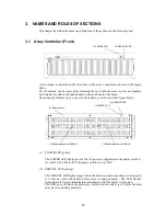
A front mask is installed on the front face of the array controller as shown in the figure
above.
The front mask can be removed by releasing the lock with the accessory key and pulling
out toward you with your hands hooked on the both sides of the mask.
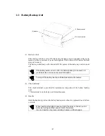
Removing the front mask, you can view the battery cover shown in the figure below.
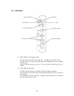
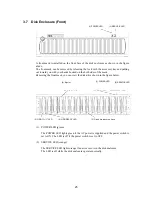
(1) POWER LED (green)
The POWER LED lights green if the AC power is supplied and the power switch is
set to ON. The LED is off if the power switch is set to OFF.
(2) SERVICE LED (orange)
The SERVICE LED lights orange when the disk array unit encounters an error, and
it is also on while the battery backup unit is being charged. The LED flashes
during the self-test and initialization immediately after the power is turned on.
The LED goes off when the disk array unit has started, and it is off while the disk
array unit is operating normally.
(1) POWER LED
(2) SERVICE LED
(2) SERVICE LED
(1) POWER LED
(3) Battery cover
(4) Battery backup unit (BBU0)
(4) Battery backup unit (BBU1)
Summary of Contents for NF2300-SR412E
Page 7: ...v ...
Page 8: ...vi ...
Page 9: ...vii ...
Page 10: ...viii ...
Page 63: ...45 ...
Page 65: ...47 Sample configuration 2 NF2300 SR4xxE NF2300 SP02E ...

