


9-56 Upgrading Your Server
Installation
1.
See the section "Preparing for Installation and Removal" described earlier to prepare.
2.
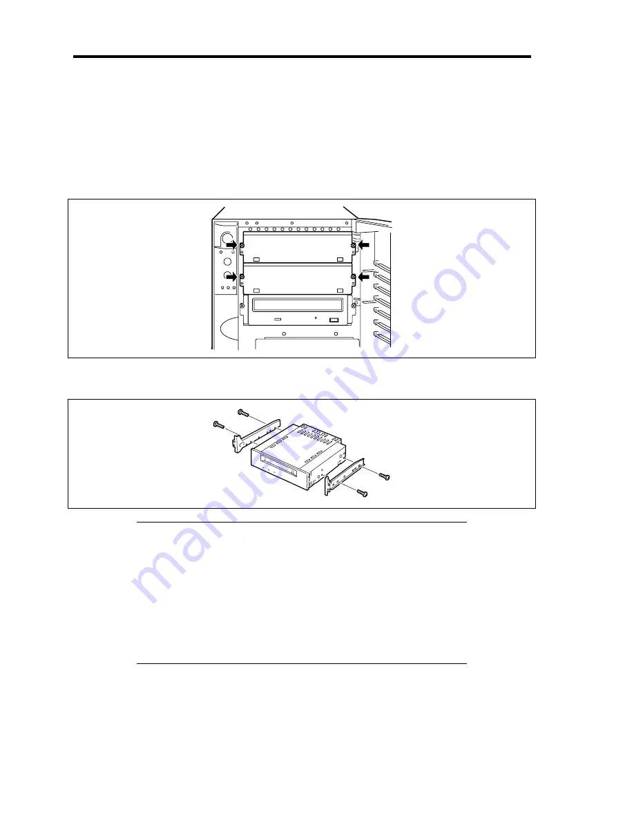
Remove the side cover.
3.
Remove the two screws fixing the dummy cover.
4.
Pull out the dummy cover toward you carefully.
5.
Fix the rails coming with the server to the 5.25-inch device by using the four screws
coming with the device.
IMPORTANT:
Always use the screws coming with the 5.25-inch device. Using
longer screws or those of different diameter may cause the device to
be broken.
Some devices have a cover on its front face. If the cover contacts
with the front door when closing the front door, move the rail
position so that the device can be seated deep in.
When installing a double-height device, use the DLT device rails
(larger L-shaped rail) that come with the server.
Summary of Contents for Express5800/120Lj
Page 16: ...x This page is intentionally left blank ...
Page 36: ...2 8 General Description Rear View 1 2 3 4 5 6 7 8 9 10 11 12 13 1 14 12 14 12 14 13 3 13 2 15 ...
Page 143: ...Configuring Your Server 4 75 3 Setting menu for VD 0 is displayed ...
Page 220: ...7 12 Maintenance This page is intentionally left blank ...
Page 352: ...9 94 Upgrading Your Server This page is intentionally left blank ...
Page 353: ...Chapter 10 Internal Cabling Diagrams Internal cable connections of the server are shown below ...
Page 360: ...10 8 Internal Cabling Diagrams This page is intentionally left blank ...
Page 362: ...A 2 Specifications This page is intentionally left blank ...
Page 370: ...C 2 IRQ This page is intentionally left blank ...
Page 426: ...F 2 Using a Client Computer Which Has a CD Drive This page is intentionally left blank ...
Page 430: ...G 4 Product Configuration Record Table This page is intentionally left blank ...


