


78K0/Fx2 – CAN it!
(4)
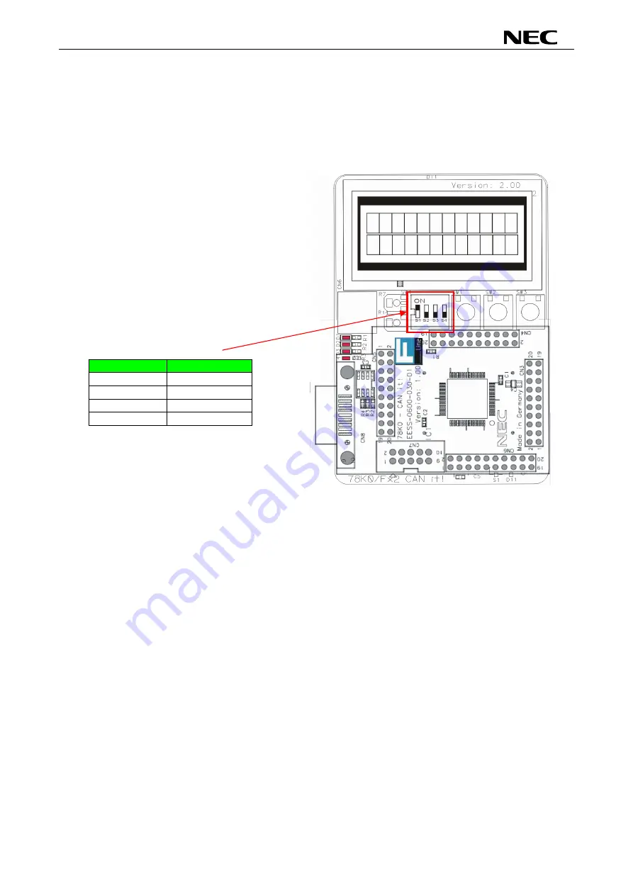
Connecting and starting
<1> Set the
78K0/Fx2 – CAN it!
board
to the FLASH programming mode by switching SW4/S1 to
ON:
<2> <Plug and Play> Connect the
78K0/Fx2 – CAN it!
board
with the host machine via the USB
cable. If the connection was already done, press the reset button SW1 to release the FLASH
programming mode.
SW4
Setting
S1 ON
S2 OFF
S3 OFF
S4 OFF
61


